308
Wiring Section 7-4
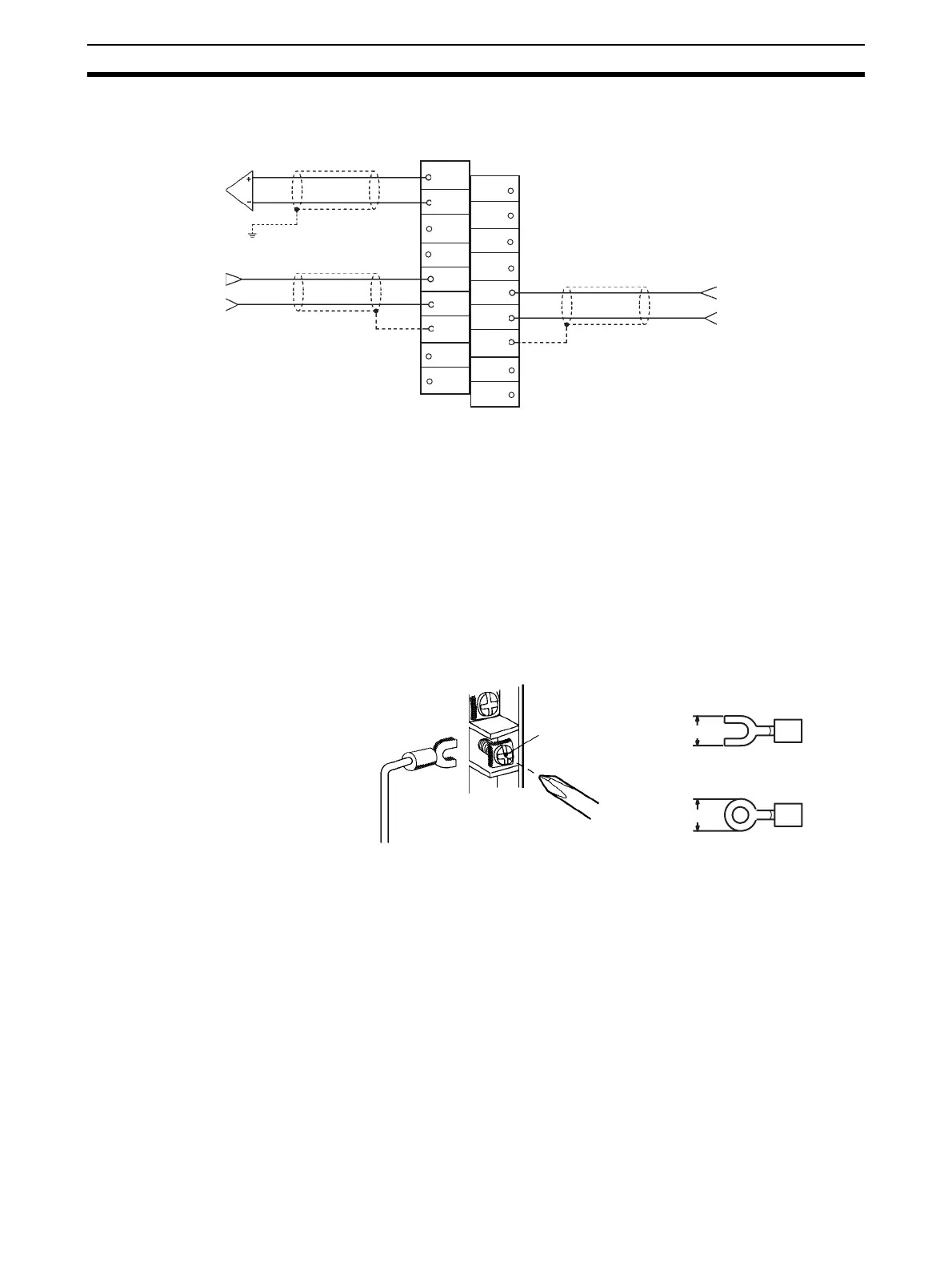
7-4-4 I/O Wiring Example
Note 1. When using current inputs, pins IN1 of the voltage/current switch must be
set to ON. Refer to 7-3-3 Voltage/Current Switch for further details. Also set
the voltage and current ranges in D(m+35) in the DM Area.
2. For inputs that are not used, either set to “0: Not used” in the input number
settings (refer to 7-6-1 Input Settings and Conversion Values) or short-cir-
cuit the voltage input terminals (V+) and (V–).
3. Crimp-type terminals must be used for terminal connections, and the
screws must be tightened securely. Use M3 screws and tighten them to a
torque of 0.5 N·m.
4. When connecting the shield of the analog input cables to the Unit’s AG ter-
minals (A7, B7), as shown in the previous diagram, use a wire that is 30 cm
max. in length if possible.
Connecting shielded cable to the Unit’s AG terminals (A7, B7) can improve
noise resistance.
To minimize output wiring noise, ground the output signal line to the input
device.
A6
A9
B1
B2
B3
B4
B5
B6
B7
B8
B9
A1
A2
A3
A4
A5
A7
A8
CJ1W-MAD42
Shield
Shield
See note 4.
Shield
+
−
+
−
Output 2
(Voltage output)
Input 2
(Voltage input)
Input 1
(Current input)
See note 4.
6.0 mm max.
6.0 mm max.
M3 screw
Fork type
Round type
 Loading...


