303
Components and Switch Settings Section 7-3
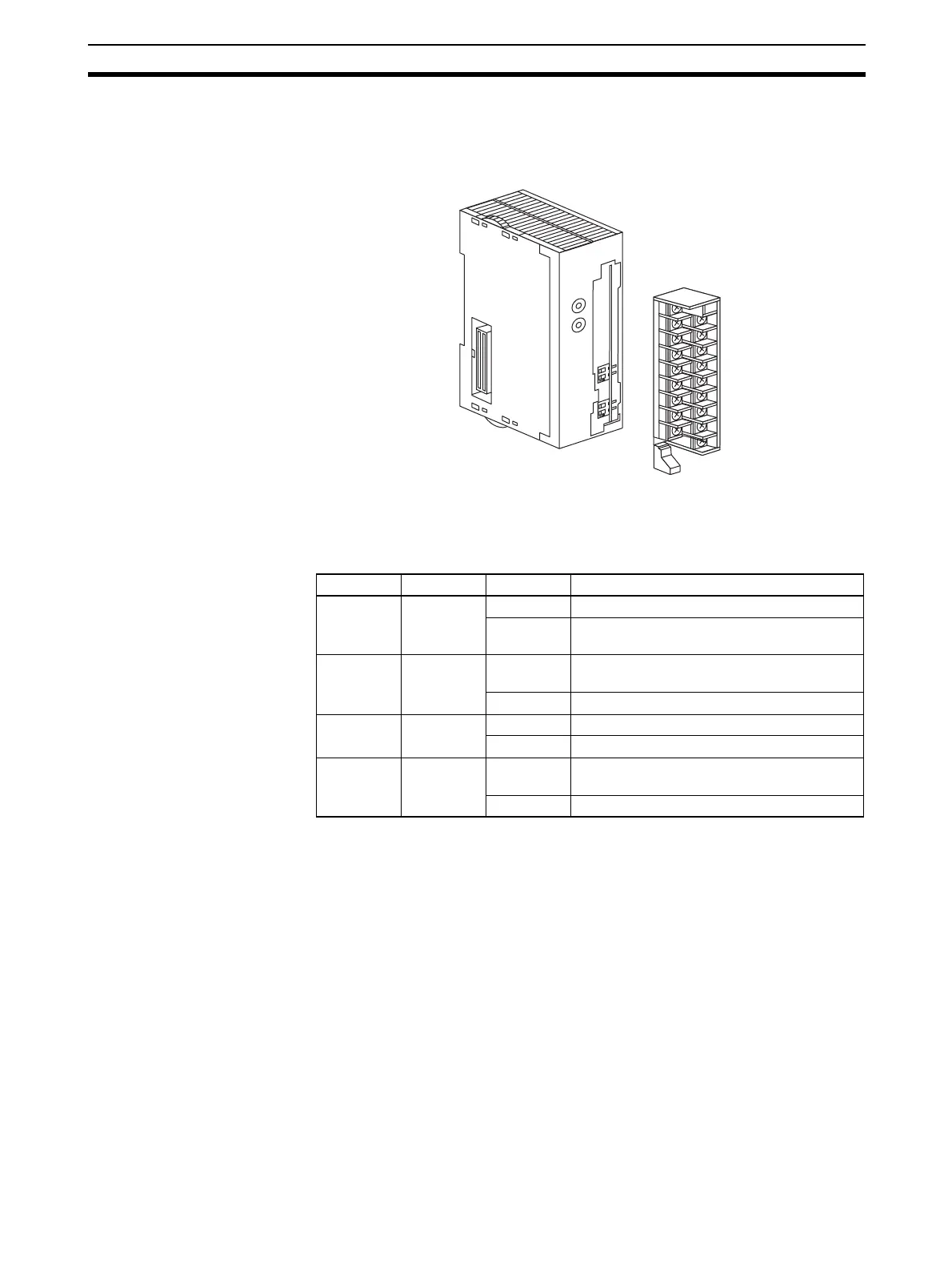
The terminal block is attached using a connector mechanism. It can be
removed by lowering the lever at the bottom of the terminal block.
The lever must normally be in the raised position. Confirm this before opera-
tion.
7-3-1 Indicators
The indicators show the operating status of the Unit. The following table
shows the meanings of the indicators.
7-3-2 Unit Number Switch
The CPU Unit and Analog I/O Unit exchange data via the Special I/O Unit
Area and the Special I/O Unit DM Area. The Special I/O Unit Area and Special
I/O Unit DM Area word addresses that each Analog I/O Unit occupies are set
by the unit number switch on the front panel of the Unit.
B1 A1
21
21
O
N
O
N
MAD42
M
A
C
H
N
o
.
1
0
1
1
0
0
R
U
N
E
RC
E
R
H
A
D
J
LED Meaning Indicator Operating status
RUN
(green)
Operating Lit Operating in normal mode.
Not lit Unit has stopped exchanging data with the
CPU Unit.
ERC (red) Error
detected by
Unit
Lit Alarm has occurred (such as disconnection
detection) or initial settings are incorrect.
Not lit Operating normally.
ADJ (yel-
low)
Adjusting Flashing Operating in offset/gain adjustment mode.
Not lit Other than the above.
ERH (red) Error in the
CPU Unit
Lit Error has occurred during data exchange
with the CPU Unit.
Not lit Operating normally.
 Loading...


