70
Handling Errors and Alarms Section 2-8
Troubleshooting
Procedure
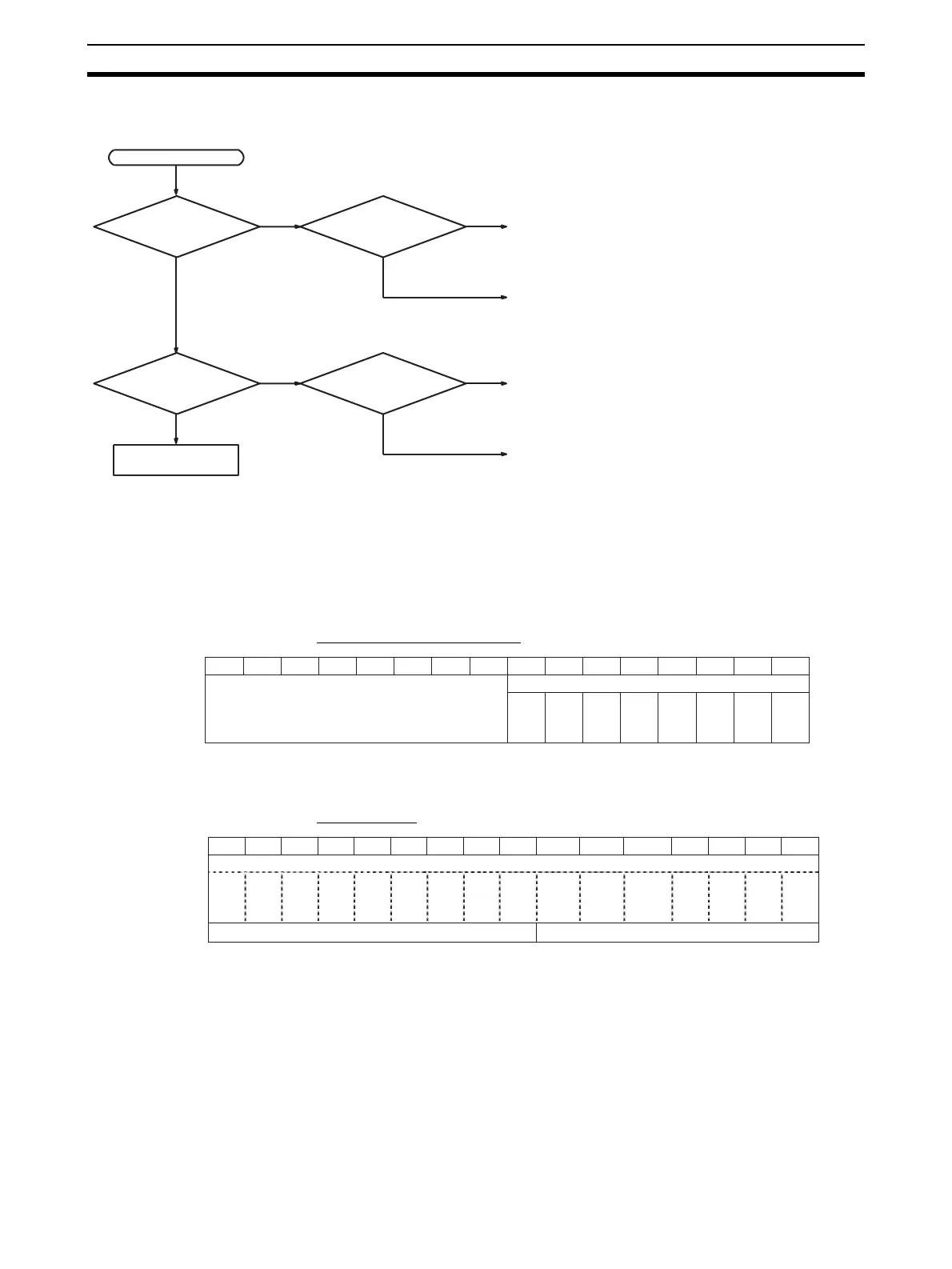
Use the following procedure for troubleshooting Analog Input Unit errors.
2-8-2 Alarms Occurring at the Analog Input Unit
If an error is detected in the Analog Input Unit, the ERC indicator will light and
the corresponding bit will turn ON.
Disconnection Detection Flags operate when the input range is set to 1 to 5 V
or 4 to 20 mA.
CS1W-AD041-V1/AD081-V1
Note Use inputs 1 to 4 for the CS1W-AD041-V1.
CS1W-AD161
Error occurs.
Is the ERC indicator
lit?
Ye s
No
Is the RUN indicator
lit?
Ye s
No
Alarm has occurred at the Analog Input Unit.
Check whether the initial settings for the Analog Input Unit
are set correctly.
Is the ERH indicator
lit?
Ye s
No
Is the RUN indicator
lit?
Ye s
No
Error detected by CPU Unit
Check whether the unit number is set correctly.
Refer to 2-8-5
Troubleshooting.
(Refer to 2-8-2 Alarms Occurring at the Analog Input Unit.)
(Refer to 2-8-2 Alarms Occurring at the Analog Input Unit.)
(Refer to 2-8-3 Errors in the CPU Unit.)
(Refer to 2-8-3 Errors in the CPU Unit.)
Bit
15 14 13 12 11 10 09 08 07 06 05 04 03 02 01 00
m = D20000 + unit number x 10
Word n+9
Alarm Flags
Disconnection Detection Flags (See note.)
Input 1
Input 2
Input 3
Input 4
Input 5
Input 6
Input 7
Input 8
15 14 13 12 11 10 08 07 06 05 04 03 02 01 00
Disconnection Detection Flags
Word n+18
Word n+19 Alarm Flags Not used.
n = CIO 2000 + unit number x 10
Bit
Input 16
Input 15
Input 14
Input 13
Input 12
Input 11
Input 10
09
Input 9
Input 8
Input 7
Input 6
Input 5
Input 4
Input 3
Input 2
Input 1
 Loading...


