326
Analog Input Functions and Operating Procedures Section 7-6
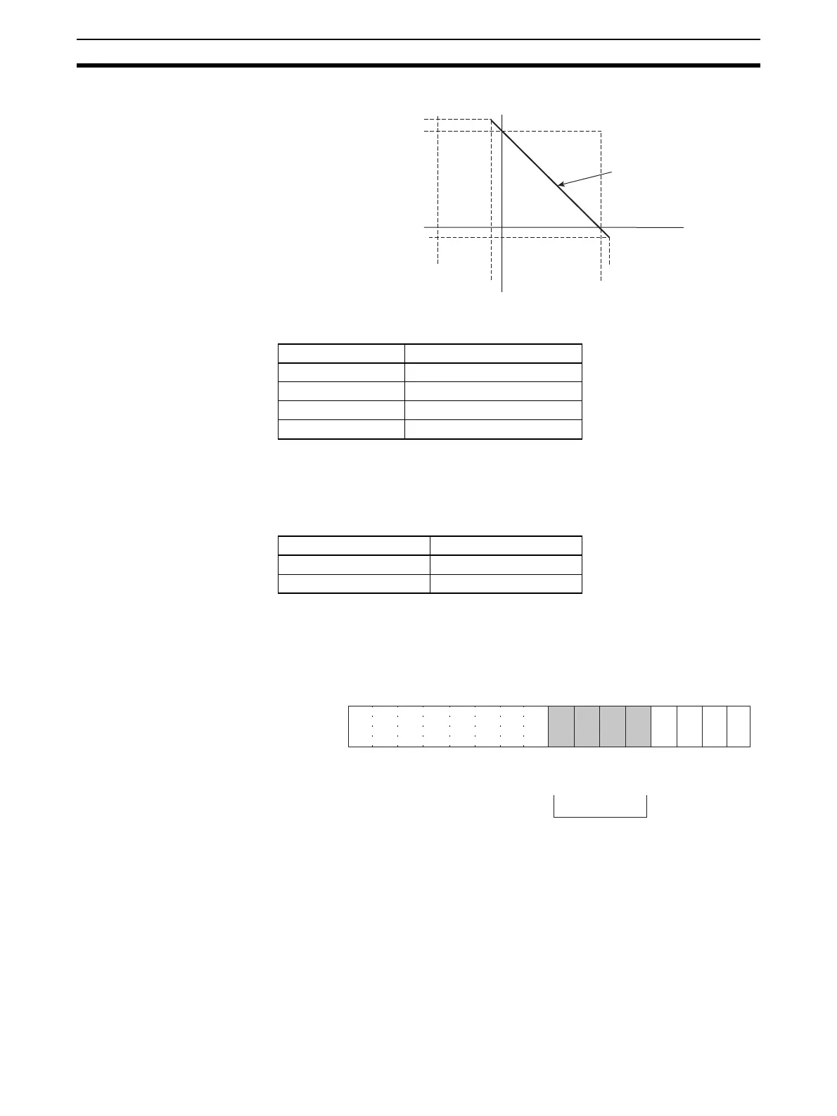
When Input Signal Range is 0 V to 10 V (Reverse Scaling)
The following table shows the correspondence between input signals and
converted scaling values. (The values shown in parentheses are binary data.)
7-6-6 Input Disconnection Detection Function
When an input signal range of 1 to 5 V (4 to 20 mA) is used, input circuit dis-
connections can be detected. The detection conditions for each of the input
signal ranges are shown in the following table.
The current/voltage level will fluctuate according to the offset/gain adjustment.
The input disconnection detection signals for each input number are stored in
bits 04 to 07 of CIO word n+9. Specify these bits as execution conditions to
use disconnection detection in the user’s program.
For the CIO word addresses, n = CIO 2000 + (unit number x 10).
The conversion value during a disconnection will be 0000.
Input signal Conversion result
0 V 10,000 (2710)
10 V 0000 (0000)
−0.5 V 10,500 (2904)
10.5 V −500 (FE0C)
Scaling line
10500 (2904)
10000 (2710)
0000 (0000)
−500 (EFC0)
0 V
−0.5 V
+10.5 V
+10 V
Range Current/voltage
1 to 5 V 0.3 V max.
4 to 20 mA 1.2 mA max.
15 14 13 12 11 10 09 08 07 06 05 04 03 02 01 00
Bit
Input 2
Input 1
Word n+9
The respective bit turns ON when a
disconnection is detected for a given
input. When the disconnection is
restored, the bit turns OFF.
Input 4
Input 3
 Loading...


