344
Adjusting Offset and Gain Section 7-9
7-9-3 Output Offset and Gain Adjustment Procedures
Specifying Output
Number to be Adjusted
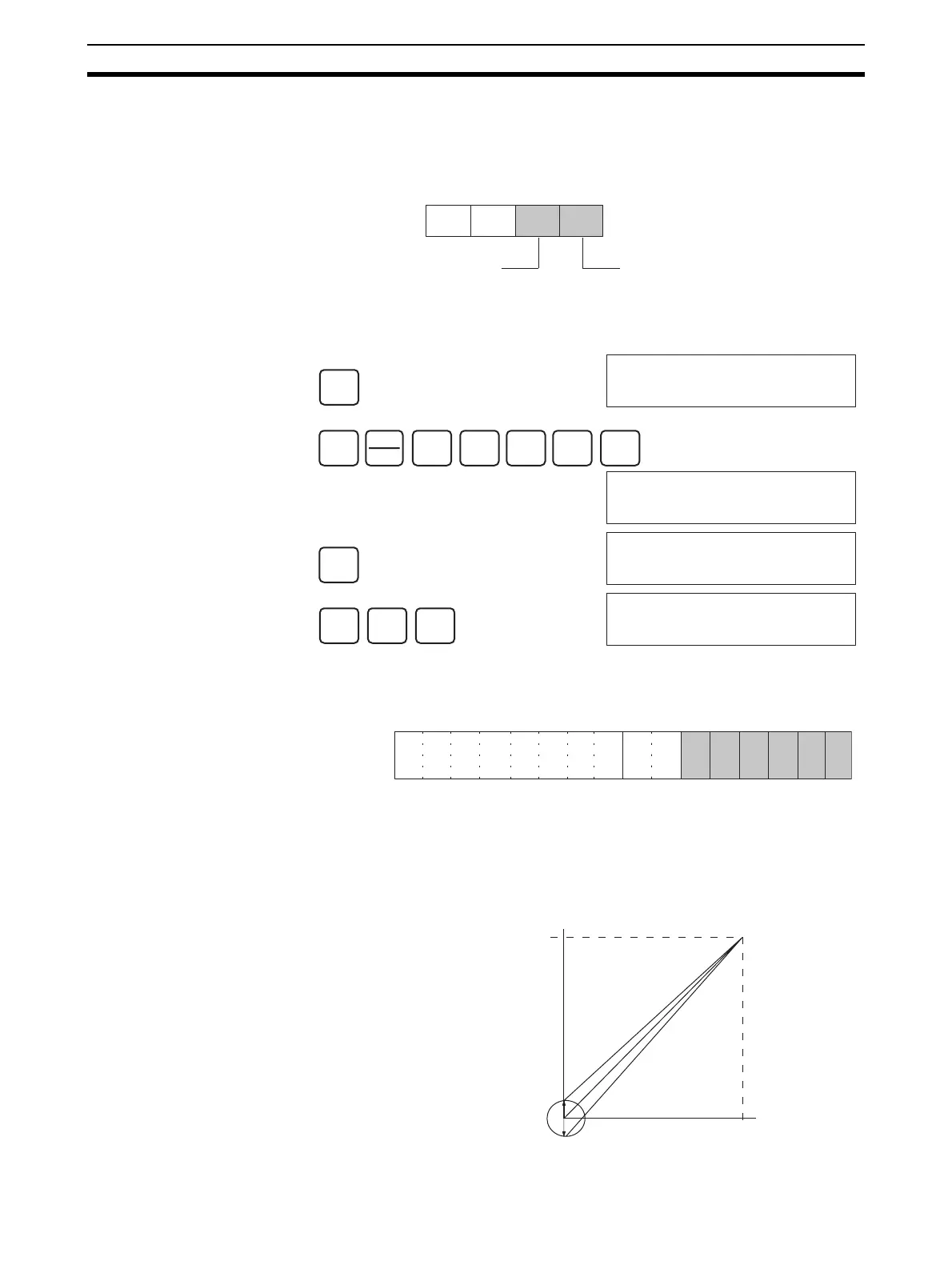
To specify the output number to be adjusted, write the value to the rightmost
byte of CIO word n as shown in the following diagram.
For the CIO word addresses, n = CIO 2000 + unit number x 10.
The following example uses output number 1 adjustment for illustration. (The
unit number is 0.)
Bits Used for Adjusting
Offset and Gain
The CIO word n+1 bits shown in the following diagram are used for adjusting
offset and gain.
Offset Adjustment The procedure for adjusting the analog output offset is explained below. As
shown in the following diagram, the set value is adjusted so that the analog
output reaches the standard value (0 V/1 V/4 mA).
(Rightmost)
(Leftmost)
Word n
Output to be adjusted (1 and 2)
--- ---
I/O specification
1: Output (fixed)
CLR
000000 CT00
SHIFT
CH
*DM
2
C
0
A
0
A
0
A
MON
2000 0000
CHG
2000 0000
PRES VAL ????
1
B
1
B
WRITE
2000 0011
15 14 13 12 11 10 09 08 07 06 05 04 03 02 01 00
Bit
Word n+1
Clear Bit
Set Bit
Up Bit
Down Bit
Gain Bit
Offset Bit
10 V
0
0FA0
Offset adjustment output ran
e
Output signal range:
0 to 10 V
 Loading...


