296
Operating Procedure Section 7-2
7-2-1 Procedure Examples
Setting the Analog I/O Unit
1,2,3... 1. Set the voltage/current switch. Refer to
7-3-3 Voltage/Current Switch for
further details.
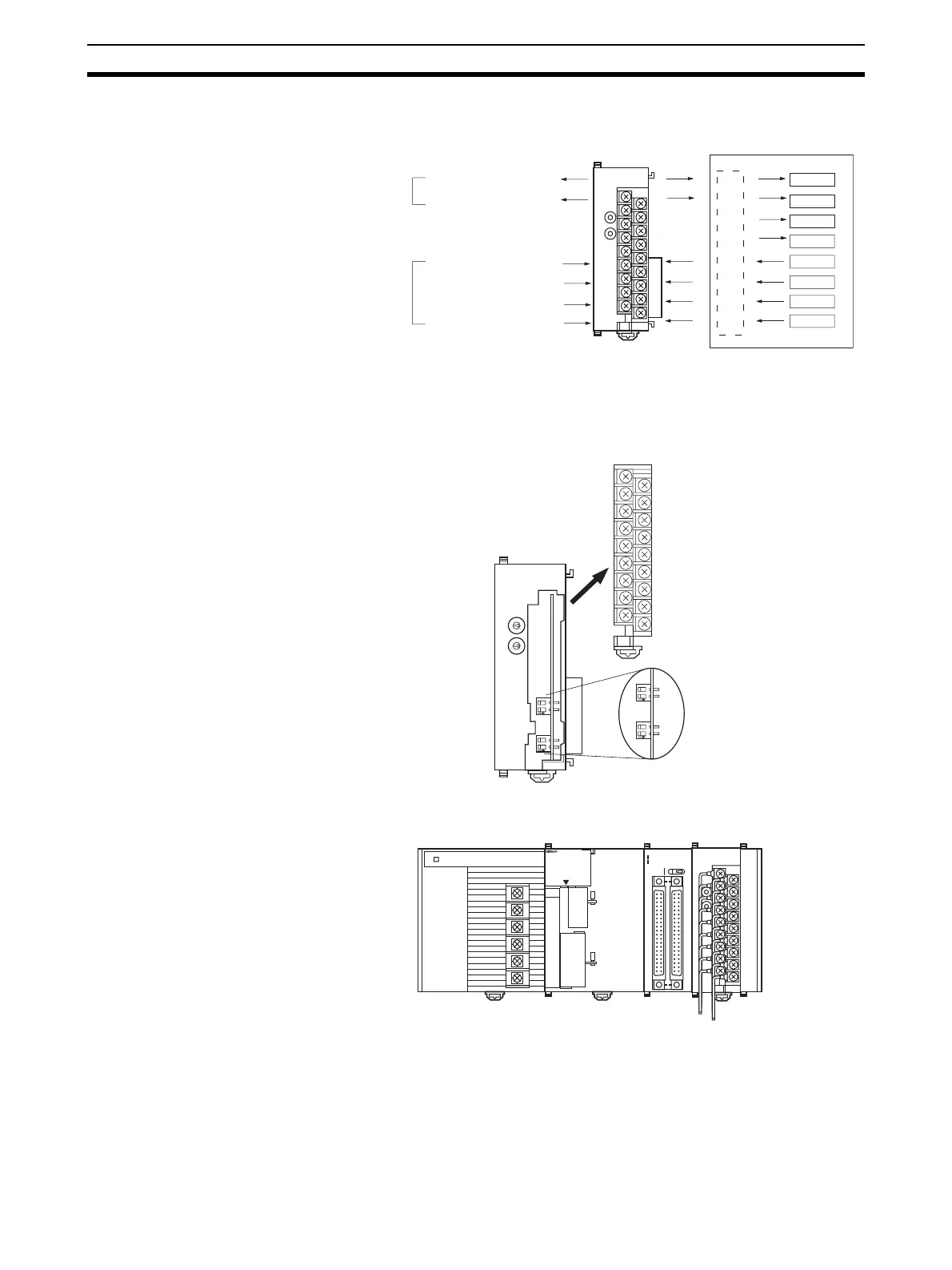
2. Mount and wire the Analog I/O Unit. Refer to 1-2-1 Mounting Procedure, 7-
4 Wiring or 7-4-4 I/O Wiring Example for further details.
CJ1W-MAD42
CJ-series CPU Unit
Unit No. 1
Analog input
Analog output
D00100
D00101
D00102
D00103
D00200
D00201
D00202
D00203
IN1: 1 to 5 V
IN2: 0 to 10 V
IN3: 4 to 20 mA
IN4: 4 to 20 mA
OUT1: 0 to 10 V
OUT2: 4 to 20 mA
Ladder Program
MAD42
B1 A1
MACH
No.
x10
1
x10
0
RUN
ERC
ERH
ADJ
RUN
ERC
ERH
B1 A1
ADJ
2121
0
9
8
7
6
5
4
3
2
1
0
9
8
7
6
5
4
3
2
1
ON
2121 ONON
ON
MACH
No.
x10
1
x10
0
MAD42
OD261
SYSMAC
CJ1G-CPU44
PROGRAMMABLE
CONTROLLER
RUN
ERR/ALM
INH
PRPHL
COMM
OPEN
PERIHERAL
PORT
MCPWR
BUSY
I
01234567
8 9 10 11 12 13 14 15
II
20
1
CN1
DC24V 0.3A
1
20
CN2
B/A A/B
I
II
0
1
2
3
01234567
8 9 10 11 12 13 14 15
MAD42
B1 A1
MACH
No.
x10
1
x10
0
RUN
ERC
ERH
ADJ
 Loading...


