297
Operating Procedure Section 7-2
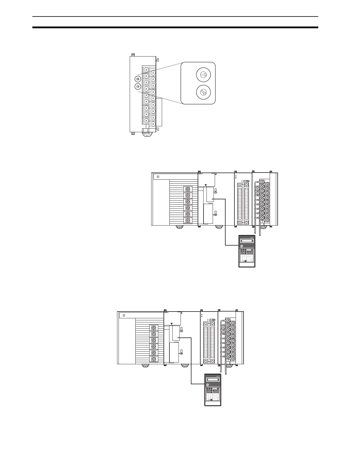
3. Set the unit number switch. Refer to 7-3-2 Unit Number Switch for further
details.
4. Turn ON the power to the PLC.
Creating I/O Tables
After turning ON the power to the PLC, be sure to create the I/O tables.
Initial Data Settings
1,2,3... 1. Specify the Special I/O Unit DM Area settings. Refer to DM Allocation and
Contents on page 312 for further details.
MACH
No.
MAD42
RUN
ERC
ERH
B1 A1
ADJ
x10
1
x10
0
0
9
8
7
6
5
4
3
2
1
0
9
8
7
6
5
4
3
2
1
MACH
No.
10
1
10
0
0
9
8
7
6
5
4
3
2
1
0
9
8
7
6
5
4
3
2
1
If the unit number is set to 1, words will
be allocated to the Analog Input Unit in
Special I/O Unit Area CIO 2010 to
CIO 2019 and in the Special I/O Unit
Area D20100 to D20199.
OD261
SYSMAC
CJ1G-CPU44
PROGRAMMABLE
CONTROLLER
RUN
ERR/ALM
INH
PRPHL
COMM
OPEN
PERIHERAL
PORT
MCPWR
BUSY
I
01234567
8 9 10 11 12 13 14 15
II
20
1
CN1
DC24V 0.3A
1
20
CN2
B/A A/B
I
II
0
1
2
3
01234567
8 9 10 11 12 13 14 15
MAD42
B1 A1
MACH
No.
x10
1
x10
0
RUN
ERC
ERH
ADJ
7
8
9
6
PRO01
PROGRAMMING CONSOLE
OR
AND
LD
OUT
TIM
CH
DM
*
EXT
5
F
4
E
1
B
2
C
3
D
0
A
TR
CNT
FUN
SFT
NOT
RUN
MONITOR
PROGRAM
LR
*
EM
EM
DM
HR
AR
Programming Consol
OD261
SYSMAC
CJ1G-CPU44
PROGRAMMABLE
CONTROLLER
RUN
ERR/ALM
INH
PRPHL
COMM
OPEN
PERIHERAL
PORT
MCPWR
BUSY
I
01234567
8 9 10 11 12 13 14 15
II
20
1
CN1
DC24V 0.3A
1
20
CN2
B/A A/B
I
II
0
1
2
3
01234567
8 9 10 11 12 13 14 15
MAD42
B1 A1
MACH
No.
x10
1
x10
0
RUN
ERC
ERH
ADJ
7
8
9
6
PRO01
PROGRAMMING CONSOLE
OR
AND
LD
OUT
TIM
CH
DM
*
EXT
5
F
4
E
1
B
2
C
3
D
0
A
TR
CNT
FUN
SFT
NOT
RUN
MONITOR
PROGRAM
LR
*
EM
EM
DM
HR
AR
Programming Console
Setting conditions
Unit No. 1
Analog input 1: 1 to 5 V
Analog input 2: 0 to 10 V
Analog input 3: 4 to 20 mA
Analog input 4: 4 to 20 mA
Analog output 1: 0 to 10 V
Analog output 2: 4 to 20 mA
 Loading...


