298
Operating Procedure Section 7-2
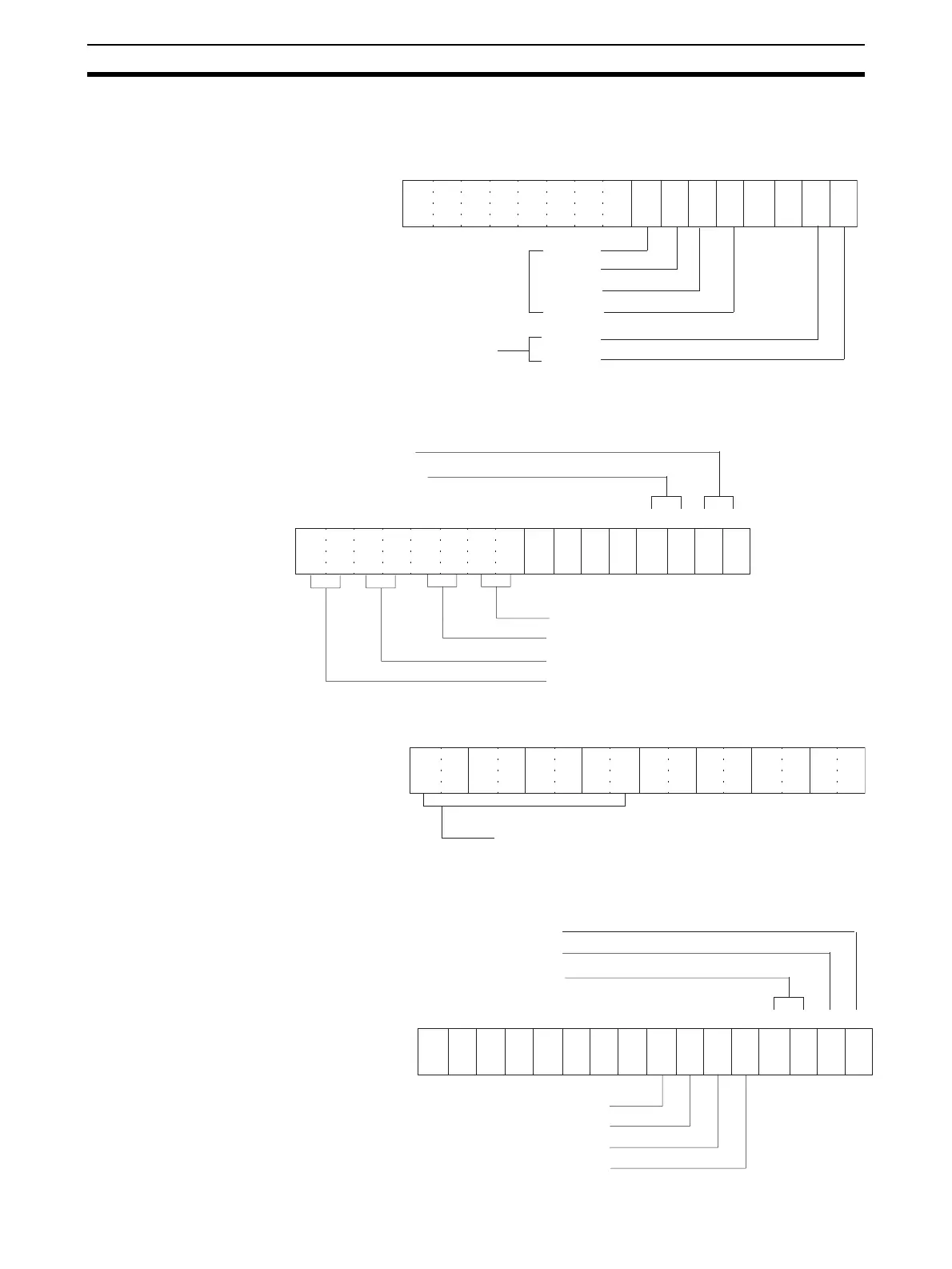
• The following diagram shows the input and output settings used. Refer
to 7-6-1 Input Settings and Conversion Values or 7-7-1 Output Settings
and Conversions for more details.
• The following diagram shows the input and output range settings. Re-
fer to 7-6-1 Input Settings and Conversion Values or 7-7-1 Output Set-
tings and Conversions for more details.
• Set the conversion time and resolution.
• Set the voltage/current range.
15 14 13 12 11 10 09 08 07 06 05 01 0004 03 02
0 0 0 0 0 0 0 0 1 1 1 1 0 0 1 1
Bit
All used
Input 4
Input 3
Input 2
Input 1
Output 2
Output 1
Used
m: DM20100
(00F7 Hex)
15 14 13 12 11 10 09 08 07 06 05 01 0004 03 02
1 0 1 0 0 1 1 0 0 0 0 0 1 0 0 1
Bit
Output 1: 0 to 10 V. Set to 01.
Output 2: 4 to 20 mA. Set to 10.
Input 1: 1 to 5 V. Set to 10.
Input 2: 0 to 10 V. Set to 01.
Input 3: 4 to 20 mA. Set to 10.
Input 4: 4 to 20 mA. Set to 10.
m+1: DM20101
(A60A Hex)
15 14 13 12 11 10 09 08 07 06 05 01 0004 03 02
0 0 0 0 0 0 0 0
Bit
Conversion Time/Resolution Setting
0000: 1-ms conversion time, 4,000 resolution
C100: 250-µs conversion time, 8,000 resolution
m+18: D20118
(0000 Hex)
15 14 13 12 11 10 09 08 07 06 05 01 0004 03 02
1 1 0 0 0 0 1 0
Bit
Output 2: Set to 1 for "4 to 20 mA" range.
Not used.
DM201035
Output 1: Set to 0 for "0 to 10 V" range.
Output 3: Set to 1 for "4 to 20 mA" range.
Output 4: Set to 1 for "4 to 20 mA" range.
Output 1: Set to 0 for "1 to 5 V" range.
Output 2: Set to 0 for "0 to 10 V" range.
 Loading...


