299
Operating Procedure Section 7-2
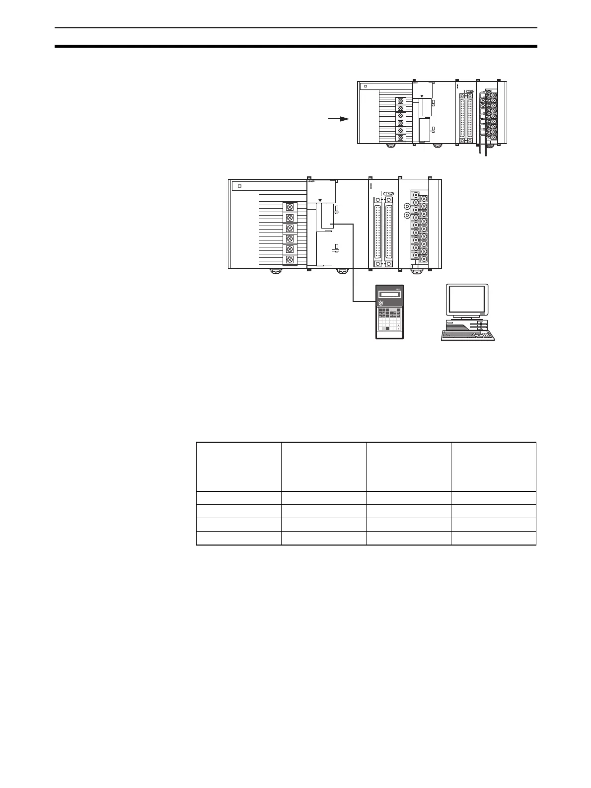
2. Restart the CPU Unit.
Creating Ladder Programs
1,2,3... 1. The following example describes how to use analog inputs.
The data that is converted from analog to digital and output to CIO words (n +
5) to (n+8) of the Special I/O Unit Area (CIO 2015 to CIO2018), is stored in
the specified addresses D00100 to D00103 as signed binary values 0000 to
0FA0 hex.
• The following table shows the addresses used for analog input.
Note a) The addresses are set according to the unit number of the Special
I/O Unit. Refer to 7-3-2 Unit Number Switch for further details.
Power turned ON again
(or Special I/O Unit Restart
Bit is turned ON).
OD261
SYSMAC
CJ1G-CPU44
PROGRAMMABLE
CONTROLLER
RUN
ERR/ALM
INH
PRPHL
COMM
OPEN
PERIHERAL
PORT
MCPWR
BUSY
I
01234567
8 9 10 11 12 13 14 15
II
20
1
CN1
DC24V 0.3A
1
20
CN2
B/A A /B
I
II
0
1
2
3
01234567
8 9 10 11 12 13 14 15
MAD42
B1 A1
MACH
No.
x10
1
x10
0
RUN
ERC
ERH
ADJ
OD261
SYSMAC
CJ1G-CPU44
PROGRAMMABLE
CONTROLLER
RUN
ERR/ALM
INH
PRPHL
COMM
OPEN
PERIHERAL
PORT
MCPWR
BUSY
I
01234567
8 9 10 11 12 13 14 15
II
20
1
CN1
DC24V 0.3A
1
20
CN2
B/A A/B
I
II
0
1
2
3
01234567
8 9 10 11 12 13 14 15
MAD42
B1 A1
MACH
No.
x10
1
x10
0
RUN
ERC
ERH
ADJ
7
8
9
6
PRO01
PROGRAMMING CONSOLE
OR
AND
LD
OUT
TIM
CH
DM
*
EXT
5
F
4
E
1
B
2
C
3
D
0
A
TR
CNT
FUN
SFT
NOT
RUN
MONITOR
PROGRAM
LR
*
EM
EM
DM
HR
AR
OR
Programming Console Personal computer
Input number Input signal range Input conversion
value address
(n = CIO 2010)
(See note 1.)
Conversion data
holding address
(See note 2.)
1 1 to 5 V (n+5) = CIO 2015 D00100
2 0 to 10 V (n+6) = CIO 2016 D00101
3 4 to 20 mA (n+7) = CIO 2017 D00102
4 4 to 20 mA (n+8) = CIO 2018 D00103
 Loading...


