203
Analog Output Functions and Operating Procedures Section 5-6
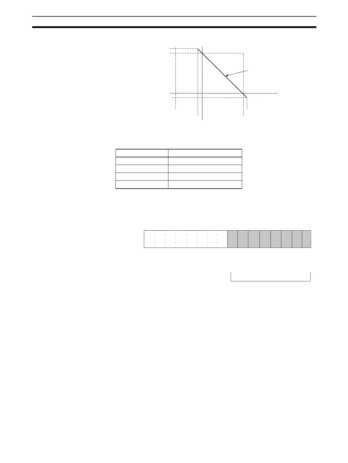
When Output Signal Range is 0 V to 10 V (Reverse Scaling)
The following table shows the correspondence between output signals and
converted scaling values. (The values shown in parentheses are 16-bit binary
data.)
5-6-6 Output Setting Errors
If the analog output set value is greater than the specified range, a setting
error signal will be stored in CIO word n+9, bits 00 to 07.
Note 1. For the CIO word addresses, n = CIO 2000 + (unit number x 10).
2. The voltage for an output number at which a setting error has occurred will
be output according to the output hold function.
Conversion result Output signal
10,000 (2710) 0 V
0000 (0000) 10 V
10,500 (2904) −0.5 V
−500 (FE0C) 10.5 V
+10.5 V
+10 V
0 V
−0.5 V
0000 (0000)
−500 (FE0C)
Scaling line
10500 (2904)
10000
2710
15 14 13 12 11 10 09 08 07 06 05 04 03 02 01 00
Bit
Output 2
Output 1
Word n+9
Output 4
Output 3
Only outputs 1 and 2 are used
by the CJ1W-DA021.
Only outputs 1 to 4 are used
by the CJ1W-DA041.
Output 6
Output 5
Output 8
Output 7
When a setting error is detected
for a particular output, the corre-
sponding bit turns ON. When the
error is cleared, the bit turns OFF.