9
Basic Configuration Section 1-2
Note The I/O bits of the Special I/O Unit are allocated according to the setting of the
unit number switch on the front panel of the Unit, and not the slot number
where the Unit is mounted.
CJ-series PLCs CJ-series Analog I/O Units are Special I/O Unit of the CJ-series PLCs.
These Units can be connected in the CJ-series CPU Rack or Expansion
Racks. The number of Analog I/O Units that can be connected in each Rack
will depend on the current consumption of the other Units in the Rack. The fol-
lowing table shows the maximum number of Analog I/O Units that can be con-
nected in one Rack if no other I/O Units are connected.
Note The I/O bits of the Special I/O Unit are allocated according to the setting of the
unit number switch on the front panel of the Unit, and not the order in which it
is connected.
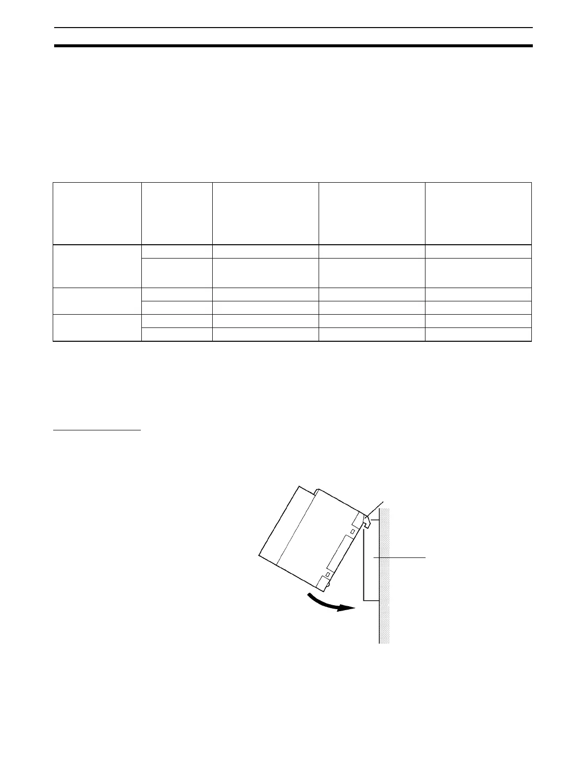
1-2-1 Mounting Procedure
CS-series PLCs
Use the following procedure to mount Analog I/O Units to the Backplane.
1,2,3... 1. Lock the top of the Analog I/O Unit into the slot on the Backplane and rotate
the Unit downwards as shown in the following diagram.
2. While making sure to align the Unit properly with the connectors, tighten
the mounting screws securely to the tightening torque of 0.4 N·m.
Power Supply Unit Rack CJ1W-DA021
CJ1W-DA041
(5 VDC 120 mA)
CJ1W-DA08V
CJ1W-DA08C
(5 VDC 140 mA)
CS1W-AD041-V1
CJ1W-AD081-V1
(5 VDC 420 mA)
CJ1W-MAD42
(5 VDC 580 mA)
CJ1W-PA205R
CJ1W-PA205C
CJ1W-PD025
(5.0 A at 5 VDC)
CPU Rack 10 9 7
Expansion Rack 10 10 8
CJ1W-PA202
(2.8 A at 5 VDC)
CPU Rack 10 4 3
Expansion Rack 10 6 4
CJ1W-PD022
(2.0 A at 5 VDC)
CPU Rack 7 2 1
Expansion Rack 10 4 3
Hook
Backplane
 Loading...


