262
Ratio Conversion Function Section 6-8
To specify the output hold function, use a Programming Device to set the DM
Area words D(m+2) to D(m+5) as shown in the following table.
For the DM word addresses, m = D20000 + (unit number x 100).
Note After specifying the DM settings from a Programming Device, it will be neces-
sary to either turn the power to the PLC OFF and ON, or turn ON the Special
I/O Unit Restart Bit to transfer the contents of the DM settings to the Special I/
O Unit.
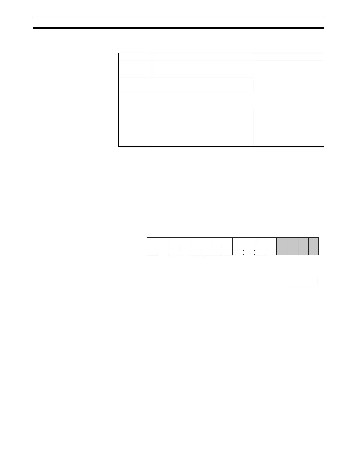
6-7-3 Output Setting Errors
If the analog output set value is greater than the specified range, a setting
error signal will be stored in CIO word n+9 (bits 00 to 03).
For the CIO word addresses, n = CIO 2000 + (unit number x 10).
The voltage for an output number at which a setting error has occurred will be
output according to the output hold function.
6-8 Ratio Conversion Function
The Analog I/O Unit has a ratio conversion function that enables it to perform
analog-to-analog conversions by itself, without utilizing the PLC. It can use
either Loop 1 (input number 1
→ output number 1), Loop 2 (input number 2 →
output number 2), Loop 3 (input number 3 → output number 3), or Loop 4
(input number 4
→ output number 4).
Input 1 → Ratio bias calculation → Output 1
Input 2
→ Ratio bias calculation → Output 2
Input 3
→ Ratio bias calculation → Output 3
Input 4 → Ratio bias calculation → Output 4
DM word Function Set value
D(m+2) Output 1: Output status when stopped xx00: CLR
Output 0 or mini-
mum value of range
(–5%).
xx01: HOLD
Hold output value
prior to stop.
xx02: MAX
Output maximum
value of range
(105%).
Set any value in the leftmost
bytes (xx).
D(m+3) Output 2: Output status when stopped
D(m+4) Output 3: Output status when stopped
D(m+5) Output 4: Output status when stopped
15 14 13 12 11 10 09 08 07 06 05 04 03 02 01 00
Bit
Output 2
Output 1
Word n+9
When a setting error is detected
for a particular output, the corre-
sponding bit turns ON. When the
error is cleared, the bit turns OFF.
Output 4
Output 3
 Loading...


