139
Wiring Section 4-4
4-4 Wiring
4-4-1 Terminal Arrangement
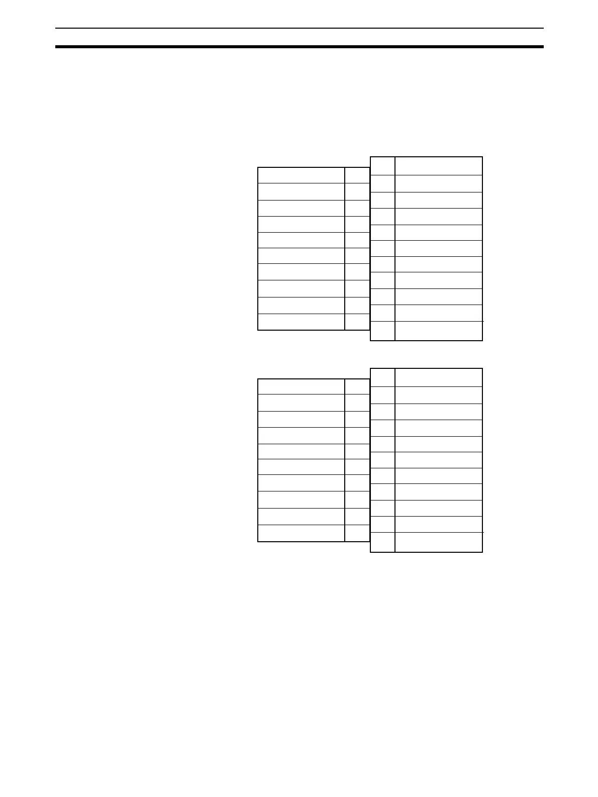
The signal names corresponding to the connecting terminals are as shown in
the following diagram.
CS1W-DA08V/08C
CS1W-DA041
Note 1. The analog output numbers that can be used are set in the Data Memory
(DM).
2. The output signal ranges for individual outputs are set in the Data Memory
(DM). They can be set in units of output numbers.
3. The N.C. terminals are not connected to internal circuitry.
Output 2 (+)
Output 2 (–)
Output 4 (+)
Output 4 (–)
Output 6 (–)
Output 8 (+)
Output 8 (–)
Output 1 (+)
Output 1 (–)
Output 3 (+)
Output 3 (–)
Output 5 (+)
Output 5 (–)
Output 7 (+)
B1
B2
B3
B4
B5
B6
B7
B8
B9
A1
A2
A3
A4
A5
A6
A7
A8
A9
B10
Output 6 (+)
Output 7 (–)
N.C.
A10
A11
N.C.
N.C.
N.C.
N.C.
Output current 2 (+)
Output 2 (–)
Output current 4 (+)
Output 4 (–)
Output current 1 (+)
Output 1 (–)
B1
B2
B3
B4
B5
B6
B7
B8
B9
A1
A2
A3
A4
A5
A6
A7
A8
A9
B10
N.C.
A10
A11
N.C.
Output voltage 2 (+)
N.C.
N.C.
Output voltage 4 (–)
N.C.
Output voltage 1 (+)
N.C.
N.C.
Output current 3 (+)
Output 3 (–)
Output voltage 3 (+)
N.C.
N.C.
 Loading...


