184
Wiring Section 5-4
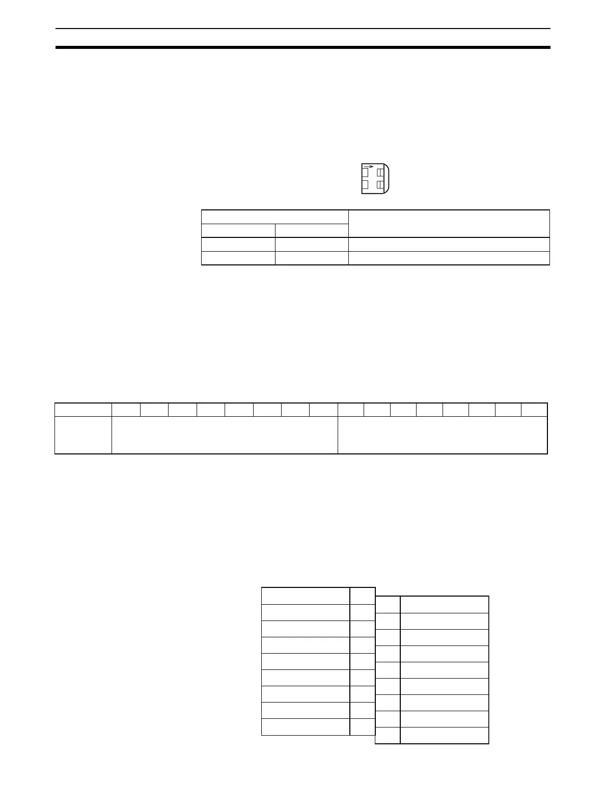
5-3-3 Operation Mode Switch (DA021/041)
The operation mode switch on the front panel of the Unit is used to set the
operation mode to either normal mode or adjustment mode (for adjusting off-
set and gain).
(The CJ1W-DA08V/08C does not have this switch. Change the mode by mak-
ing the setting in bits 00 to 07 of DM word m+18. Set 00 for adjustment mode
or 01 for normal mode.)
!Caution Do not set the pins to any combination other than those shown in the above
table. Be sure to set pin 2 to OFF.
!Caution Be sure to turn OFF the power to the PLC before installing or removing the
Unit.
Note The CJ1W-DA08V/08C Analog Output Unit has a software setting for the
operation mode in bits 00 to 07 of DM word m+18. The contents of DM word
m+18 are shown below.
m = D20000 + (unit number x 100)
5-4 Wiring
5-4-1 Terminal Arrangement
The signal names corresponding to the connecting terminals are as shown in
the following diagram.
CJ1W-DA021
Pin number Mode
12
OFF OFF Normal mode
ON OFF Adjustment mode
O
N
12
MODE
Bit 15 14 13 12 11 10 09 08 0706050403020100
D (m+18) Conversion time/resolution setting
00: Conversion time of 1 ms and resolution of 4,000
C1: Conversion time of 250 µs and resolution of 8,000
Operation mode setting
00: Normal mode
C1: Adjustment mode
Voltage output 2 (+)
Output 2 (–)
Current output 2 (+)
N.C.
N.C.
N.C.
N.C.
N.C.
0 V
Voltage output 1 (+)
Output 1 (–)
Current output 1 (+)
N.C.
N.C.
N.C.
N.C.
N.C.
24 V
B1
B2
B3
B4
B5
B6
B7
B8
B9
A1
A2
A3
A4
A5
A6
A7
A8
A9
 Loading...


