30
Components and Switch Settings Section 2-3
Note 1. If two or more Special I/O Units are assigned the same unit number, a
“UNIT No. DPL ERR” error (in the Programming Console) will be generat-
ed (A40113 will turn ON) and the PLC will not operate.
2. A single CS1W-AD161 is allocated CIO Area words and DM Area words
for two Units. Be sure to set a unit number so that the CS1W-AD161 is not
allocated words in the CIO Area and DM Area that are already allocated to
other Special I/O Units. For example, if the CS1W-AD161 is set to unit
number n, another Special I/O Unit cannot be set with unit number n+1.
The highest unit number that can be set for a CS1W-AD161 is unit number
94.
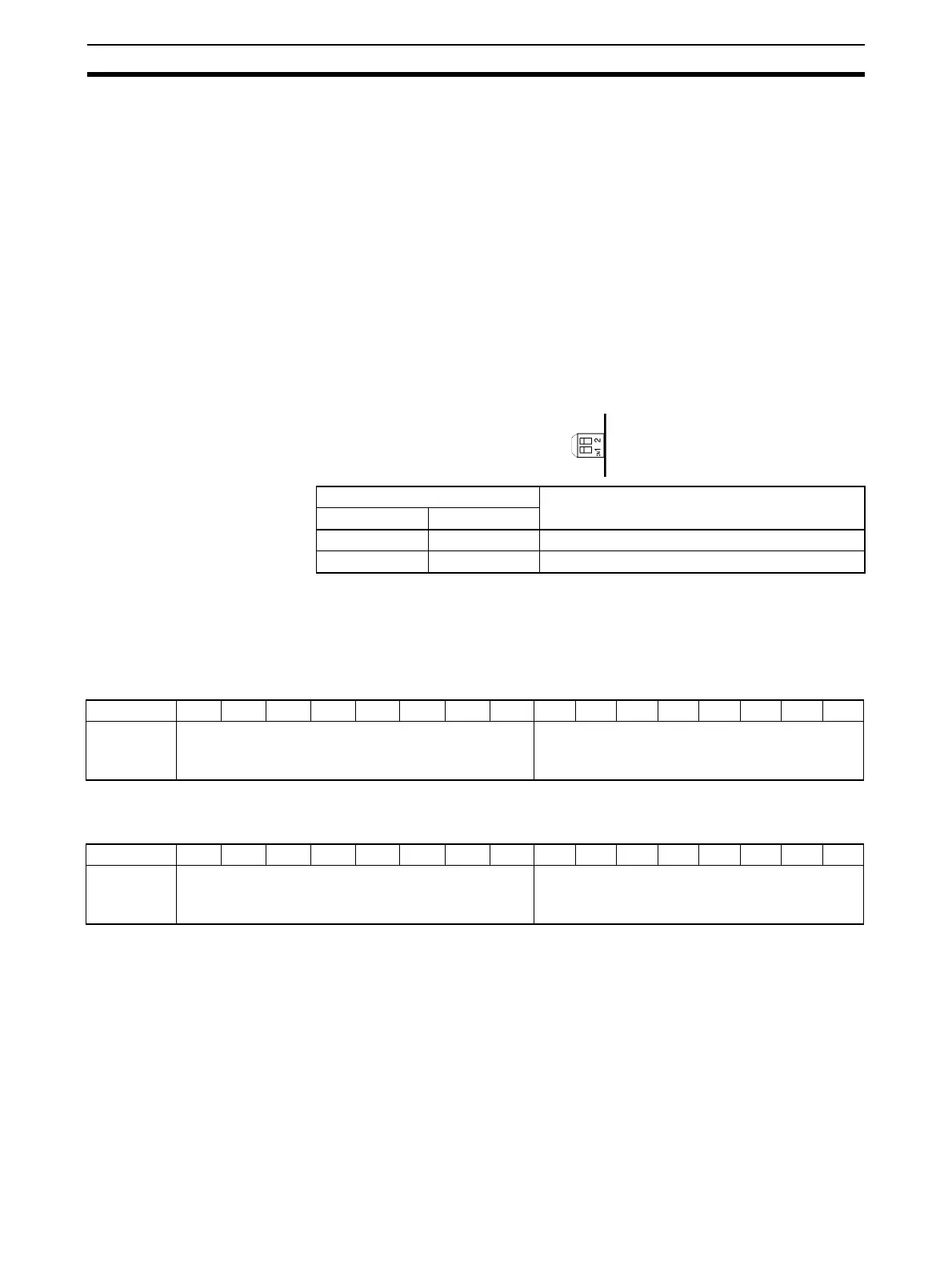
2-3-3 Operation Mode Switch
The operation mode switch on the back panel of the Unit is used to set the
operation mode to either normal mode or adjustment mode (for adjusting off-
set and gain).
Note 1. The operation mode can be set in the DM Area as an alternative to using
the operation mode switch.
2. Set the operation mode in DM word m+18 for CS1W-AD041-V1 and
CS1W-AD081-V1, and in DM word m+19 for CS1W-AD161.
CS1W-AD041-V1/AD081-V1
m = D20000 + (unit number x 100)
CS1W-AD161
m = D20000 + (unit number x 100)
Pin number Mode
12
OFF OFF Normal mode
ON OFF Adjustment mode
Bit 15 14 13 12 11 10 09 08 0706050403020100
D (m+18) Conversion time/resolution setting Operation mode setting
00: Normal mode
C1: Adjustment mode
Bit 15 14 13 12 11 10 09 08 0706050403020100
D (m+19) Conversion time/resolution setting Operation mode setting
00: Normal mode
C1: Adjustment mode
 Loading...


