147
Exchanging Data with the CPU Unit Section 4-5
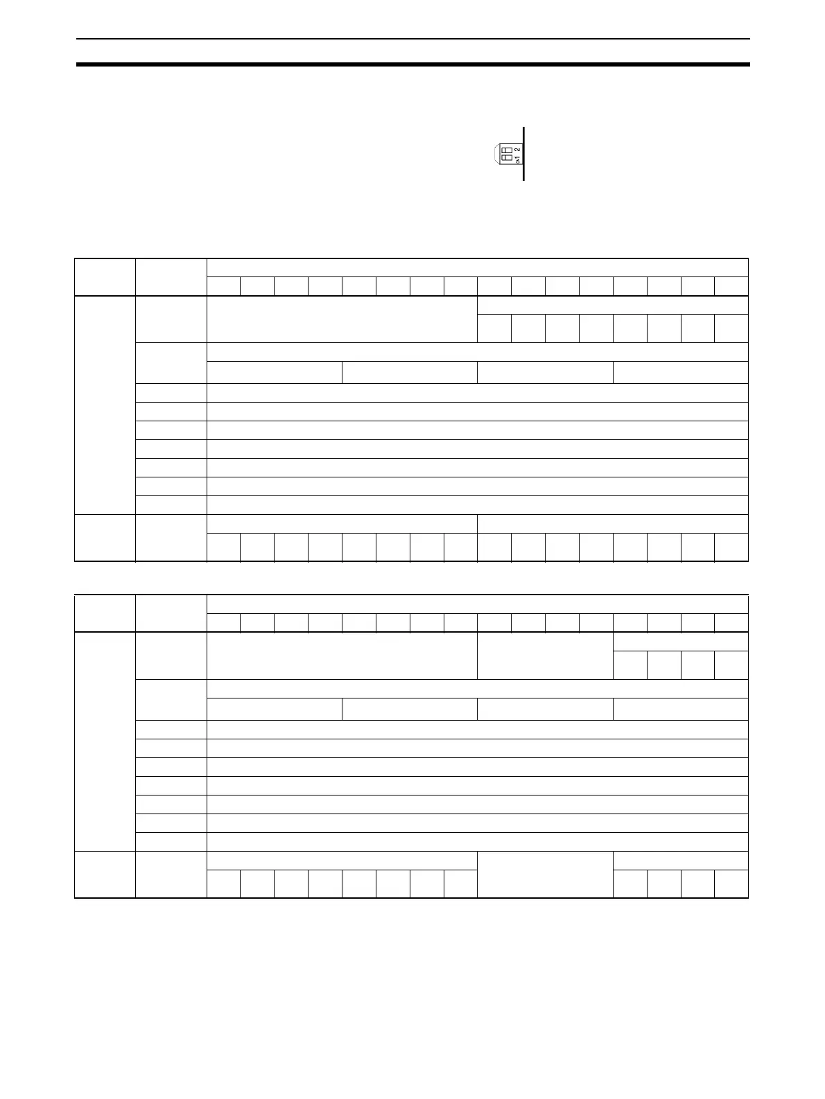
Allocations for Normal
Mode
For normal mode, set the operation mode switch on the rear panel of the Unit
as shown in the following diagram.
The allocation of words and bits in the CIO Area is shown in the following
table.
CS1W-DA08V/08C
CS1W-DA041
Note For the CIO word addresses, n = CIO 2000 + unit number x 10.
I/O Word Bits
1514131211109876543210
Output
(CPU to
Unit)
n Not used. Conversion enable
Out-
put 8
Out-
put 7
Out-
put 6
Out-
put 5
Out-
put 4
Out-
put 3
Out-
put 2
Out-
put 1
n + 1 Output 1 set value
16
3
16
2
16
1
16
0
n + 2 Output 2 set value
n + 3 Output 3 set value
n + 4 Output 4 set value
n + 5 Output 5 set value
n + 6 Output 6 set value
n + 7 Output 7 set value
n + 8 Output 8 set value
Input
(Unit to
CPU)
n + 9 Alarm Flags Output setting error
Out-
put 8
Out-
put 7
Out-
put 6
Out-
put 5
Out-
put 4
Out-
put 3
Out-
put 2
Out-
put 1
I/O Word Bits
1514131211109876543210
Output
(CPU to
Unit)
n Not used. Not used. Conversion enable
Out-
put 4
Out-
put 3
Out-
put 2
Out-
put 1
n + 1 Output 1 set value
16
3
16
2
16
1
16
0
n + 2 Output 2 set value
n + 3 Output 3 set value
n + 4 Output 4 set value
n + 5 Not used.
n + 6 Not used.
n + 7 Not used.
n + 8 Not used.
Input
(Unit to
CPU)
n + 9 Alarm Flags Not used. Output setting error
Out-
put 4
Out-
put 3
Out-
put 2
Out-
put 1
 Loading...


