159
Adjusting Offset and Gain Section 4-7
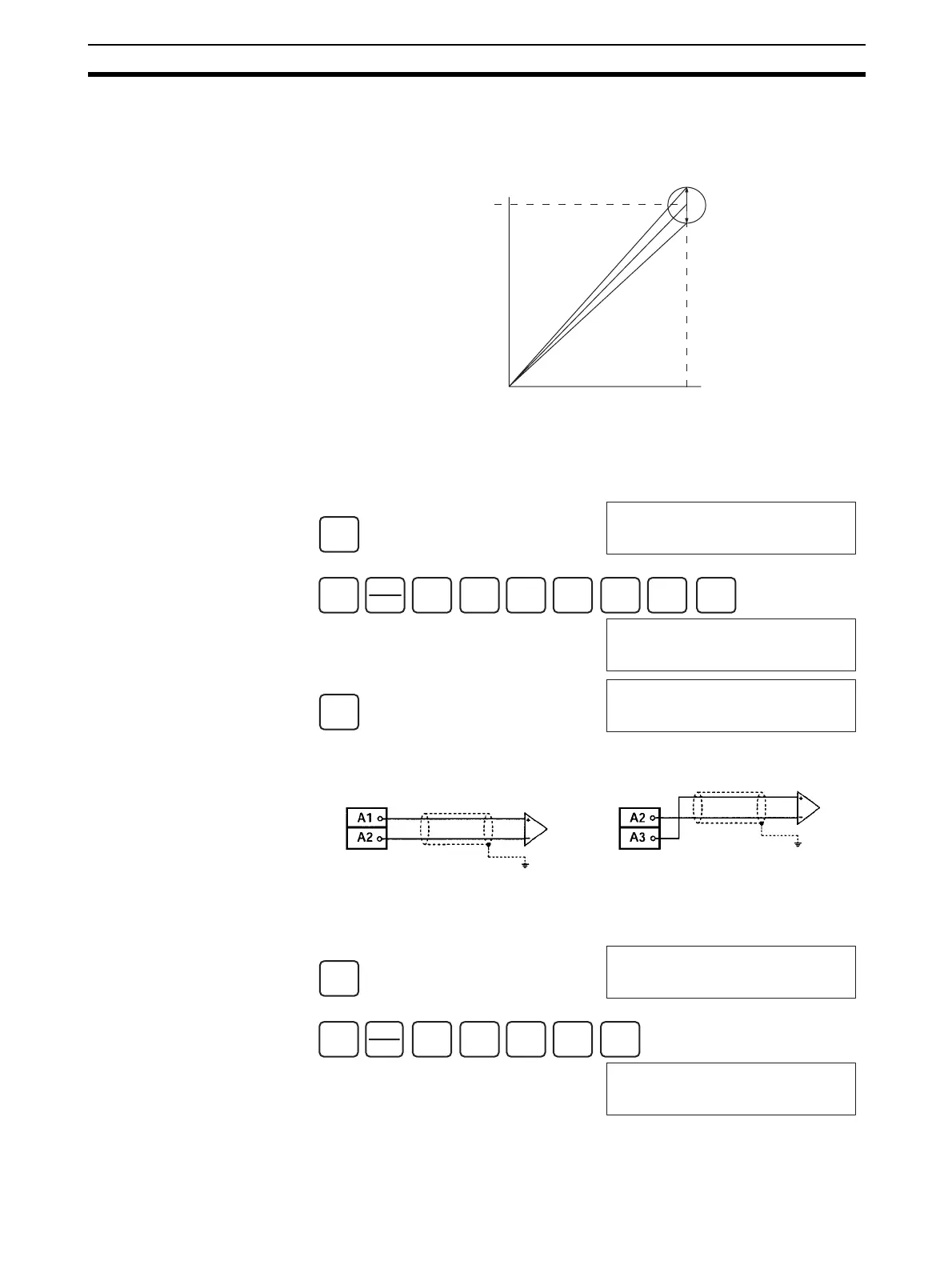
Gain Adjustment The procedure for adjusting the analog output gain is explained below. As
shown in the following diagram, the set value is adjusted so that the analog
output is maximized (to 10 V/5 V/20 mA).
The following example uses output number 1 adjustment for illustration. (The
unit number is 0.)
1,2,3... 1. Turn ON bit 01 (the Gain Bit) of CIO word n+1. (Hold the ON status.)
2. Check whether the output devices are connected.
3. Monitor CIO word n+8 and check the set value while the Gain Bit is ON.
10 V
0
0FA0
Output signal range:
0 to 10 V
Gain adjustment output range
CLR
000000 CT00
SHIFT
CONT
#
2
C
0
A
0
A
1
B
0
A
1
B
MON
200101 ^ OFF
SET
200101 ^ ON
Voltage output/current output
Output 1
CS1W-DA08V/08C
CS1W-DA041 (voltage output)
Current output
CS1W-DA041 (current output)
CLR
000000 CT00
SHIFT
CH
*DM
2
C
0
A
0
A
8
MON
2008 0000
 Loading...


