212
Adjusting Offset and Gain Section 5-7
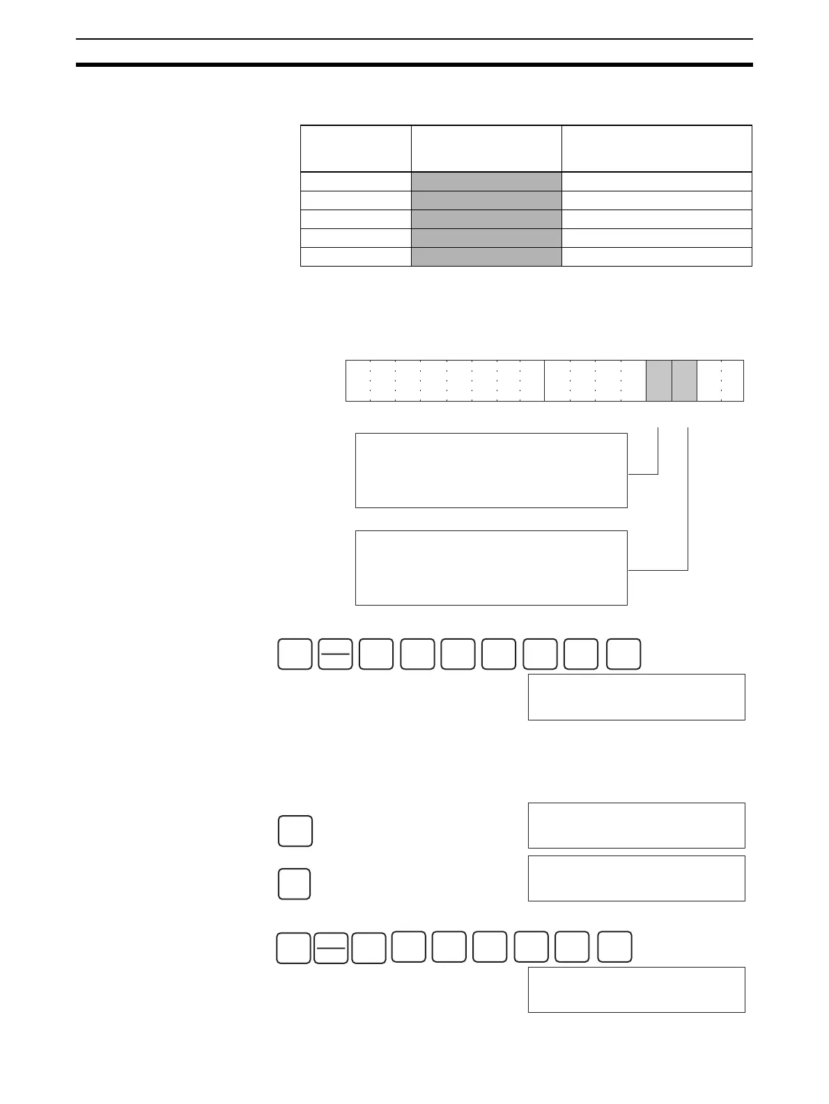
4. Change the set value so that the output voltage is as shown in the following
table. The data can be set within the indicated ranges.
Change the set value, using the Up Bit (bit 03 of word n+1) and the Down
Bit (bit 02 of word n+1).
• The following example increases the output voltage.
The bit will remain ON until the output voltage becomes an appropriate val-
ue, at which time, the output will turn OFF.
• The following example decreases the output voltage.
Output signal
range
Possible output
voltage/current
adjustment
Output range
0 to 10 V 9.5 to 10.5 V 0ED8 to 1068 (1DB0 to 20D0)
–10 to 10 V
9 to 11 V 0708 to 0898 (0E10 to 1130)
1 to 5 V
4.8 to 5.2 V 0ED8 to 1068 (1DB0 to 20D0)
0 to 5 V
4.75 to 5.25 V 0ED8 to 1068 (1DB0 to 20D0)
4 to 20 mA
19.2 to 20.8 mA 0ED8 to 1068 (1DB0 to 20D0)
(Values in parentheses are for a resolution of 8,000.)
15 14 13 12 11 10 09 08 07 06 05 04 03 02 01 00
Bit
Up Bit Down Bit
While the Up Bit is ON, the set value will be
increased by 1 resolution every 0.5 seconds.
After it has been ON for 3 seconds, the set
value will be increased by 1 resolution every
0.1 seconds.
While the Down Bit is ON, the set value will be
decreased by 1 resolution every 0.5 seconds.
After it has been ON for 3 seconds, the set
value will be decreased by 1 resolution every
0.1 seconds.
Word n+1
SHIFT
CONT
#
2
C
0
A
0
A
1
B
0
A
3
D
MON
200103 ^ OFF
SET
200103 ^ ON
RESET
200103 ^ OFF
SHIFT
CONT
#
2
C
0
A
0
A
1
B
0
A
2
C
MON
200102 ^ OFF
 Loading...


