332
Analog Output Functions and Operating Procedures Section 7-7
Setting Upper and Lower
Limits for Output Scaling
Set the scaling upper and lower limits for outputs 1 and 2 in words D(m+19) to
D(m+22) of the DM Area, as shown below.
Note For decimal numbers
−32,000 to +32,000, set 16-bit binary data (8300 to
7D00).
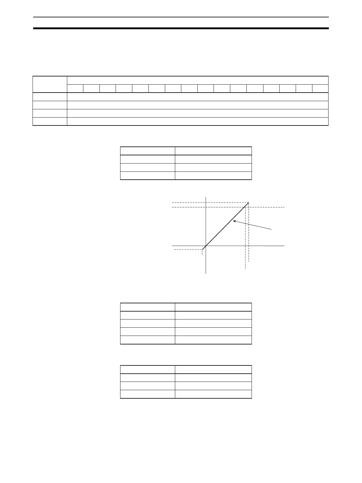
Example Setting 1 Set the following conditions in D(m+19) to D(m+22). (The values shown in
parentheses are binary data.)
When Output Signal Range is 0 V to 10 V
The following table shows the correspondence between output signals and
converted scaling values. (The values shown in parentheses are 16-bit binary
data.)
Example Setting 2
(Reverse Scaling)
Set the following conditions in D(m+27) to D(m+34). (The values shown in
parentheses are binary data.)
DM word Bits
1514131211109876543210
D(m+19) Output 1 scaling lower limit
D(m+20) Output 1 scaling upper limit
D(m+21) Output 2 scaling lower limit
D(m+22) Output 2 scaling upper limit
Setting condition Set value
Output signal range 0 to 10 V
Scaling lower limit 0000 (0000)
Scaling upper limit 10,000 (2710)
Output set value Output signal
0000 (0000) 0 V
10,000 (2710) 10 V
−500 (FE0C) −0.5 V
10,500 (2904) 10.5 V
+10.5 V
+10 V
0 V
−0.5 V
0000 (0000)
−500 (FE0C)
Scaling line
10500 (2904)
10000 (2710)
Setting condition Set value
Output signal range 0 to 10 V
Scaling lower limit 10000 (2710)
Scaling upper limit 0000 (0000)
 Loading...


