EasyManua.ls Logo

Omron CS1W-AD081-V1 User Manual

Omron CS1W-AD081-V1
427 pages
To Next Page IconTo Next Page
To Previous Page IconTo Previous Page
Page #76 background imageLoading...
Page #76 background image
53
Analog Input Functions and Operating Procedures Section 2-6
00: 10 to +10 V
01: 0 to 10 V
10: 1 to 5 V/4 to 20 mA (See note 2.)
11: 0 to 10 V
Select the input signal range 1 to 5 V/4 to 20 mA by wiring the connector or
terminal block conversion connector. The voltage/current input setting can
also be set using DM word m+52.
0: 1 to 5 V
1: 4 to 20 mA
Note 1. For the DM word addresses, m = D20000 + (unit number x 100)
2. The input signal range of “1 to 5 V” or “4 to 20 mA” is switched using the
voltage/current switch.
3. After making the DM settings from a Programming Device, it will be neces-
sary to either turn the power to the PLC OFF and ON, or turn ON the Spe-
cial I/O Unit Restart Bit in order to transfer the contents of the DM settings
to the Special I/O Unit.
Reading Conversion
Values
Analog input conversion values are read in 4-digit hexadecimal for each input.
Note For the CIO word addresses, n = CIO 2000 + (unit number x 10).
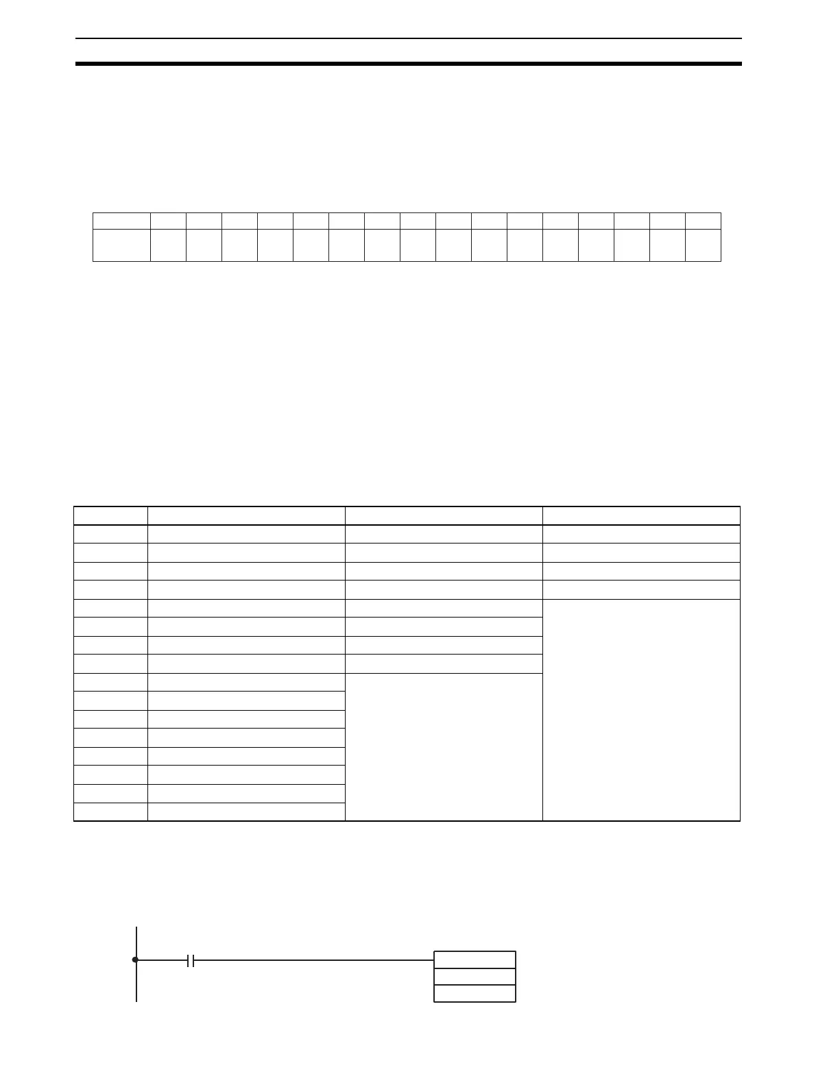
Use MOV(021) or XFER(070) to read conversion values in the user program.
Example 1 In this example, the conversion data from only one input is read. (The unit
number is 0.)
Bit 15 14 13 12 11 10 09 08 07 06 05 04 03 02 01 00
D (m+52) Input
16
Input
15
Input
14
Input
13
Input
12
Input
11
Input
10
Input
9
Input
8
Input
7
Input
6
Input
5
Input
4
Input
3
Input
2
Input
1
m = D20000 + unit number x 100
Address CS1W-AD161 CS1W-AD081-V1 CS1W-AD041-V1
n+1 Input 1 conversion value Input 1 conversion value Input 1 conversion value
n+2 Input 2 conversion value Input 2 conversion value Input 2 conversion value
n+3 Input 3 conversion value Input 3 conversion value Input 3 conversion value
n+4 Input 4 conversion value Input 4 conversion value Input 4 conversion value
n+5 Input 5 conversion value Input 5 conversion value Cannot be used.
n+6 Input 6 conversion value Input 6 conversion value
n+7 Input 7 conversion value Input 7 conversion value
n+8 Input 8 conversion value Input 8 conversion value
n+9 Input 9 conversion value Cannot be used.
n+10 Input 0 conversion value
n+11 Input 1 conversion value
n+12 Input 12 conversion value
n+13 Input 13 conversion value
n+14 Input 14 conversion value
n+15 Input 15 conversion value
n+16 Input 16 conversion value
MOV(021)
2001
D00001
Input condition
Conversion data in CIO word
2001 (input number 1) is read
to D 00001.

Table of Contents

Questions and Answers:

Omron CS1W-AD081-V1 Specifications

General IconGeneral
Number of Channels8
Power Supply5 V DC
Operating Temperature0 to 55 °C
TypeAnalog Input
Input Range0 to 10 V, 0 to 20 mA, 4 to 20 mA
Sampling Time/Conversion Time1ms per channel
Current Consumption100 mA
IsolationPhotocoupler isolation between input and internal circuit
Storage Temperature-25 to 65 °C
Relative Humidity35 to 85% (with no condensation)
Noise Immunity±2 kV
StandardsCE, UL

Summary

SYSMAC CS/CJ Series

Analog I/O Units

Describes the types of analog I/O units covered in the manual, including input, output, and combined units.

PRECAUTIONS

General Precautions

Fundamental safety and operational guidelines for using OMRON products.

Safety Precautions

Critical safety warnings and procedures to prevent injury or damage.

Application Considerations

SECTION 2 CS-series Analog Input Units

2-2 Operating Procedure

Step-by-step instructions for operating CS-series Analog Input Units.

2-6 Analog Input Functions and Operating Procedures

Details on analog input functions and their operational procedures.

2-8 Handling Errors and Alarms

Troubleshooting guide for errors and alarms in Analog Input Units.

SECTION 3 CJ-series Analog Input Units

3-2 Operating Procedure

Step-by-step instructions for operating CJ-series Analog Input Units.

3-6 Analog Input Functions and Operating Procedures

Details on analog input functions and their operational procedures.

3-8 Handling Errors and Alarms

Troubleshooting guide for errors and alarms in Analog Input Units.

SECTION 4 CS-series Analog Output Units

4-2 Operating Procedure

Step-by-step instructions for operating CS-series Analog Output Units.

4-6 Analog Output Functions and Operating Procedures

Details on analog output functions and their operational procedures.

4-8 Handling Errors and Alarms

Troubleshooting guide for errors and alarms in Analog Output Units.

SECTION 5 CJ-series Analog Output Unit

5-2 Operating Procedure

Step-by-step instructions for operating CJ-series Analog Output Units.

5-6 Analog Output Functions and Operating Procedures

Details on analog output functions and their operational procedures.

5-8 Handling Errors and Alarms

Troubleshooting guide for errors and alarms in Analog Output Units.

SECTION 6 CS-series Analog I/O Unit

6-2 Operating Procedure

Step-by-step instructions for operating CS-series Analog I/O Units.

6-6 Analog Input Functions and Operating Procedures

Details on analog input functions and their operational procedures.

6-7 Analog Output Functions and Operating Procedures

Details on analog output functions and their operational procedures.

6-10 Handling Errors and Alarms

Troubleshooting guide for errors and alarms in Analog I/O Units.

SECTION 7 CJ-series Analog I/O Unit

7-2 Operating Procedure

Step-by-step instructions for operating CJ-series Analog I/O Units.

7-6 Analog Input Functions and Operating Procedures

Details on analog input functions and their operational procedures.

7-7 Analog Output Functions and Operating Procedures

Details on analog output functions and their operational procedures.

7-10 Handling Errors and Alarms

Troubleshooting guide for errors and alarms in Analog I/O Units.

Appendix B Sample Programs

Appendix C Data Memory Coding Sheets

Related product manuals