Tool Flange Replacement Procedure
Use the following procedure to replace the tool flange on the z-axis quill if necessary.
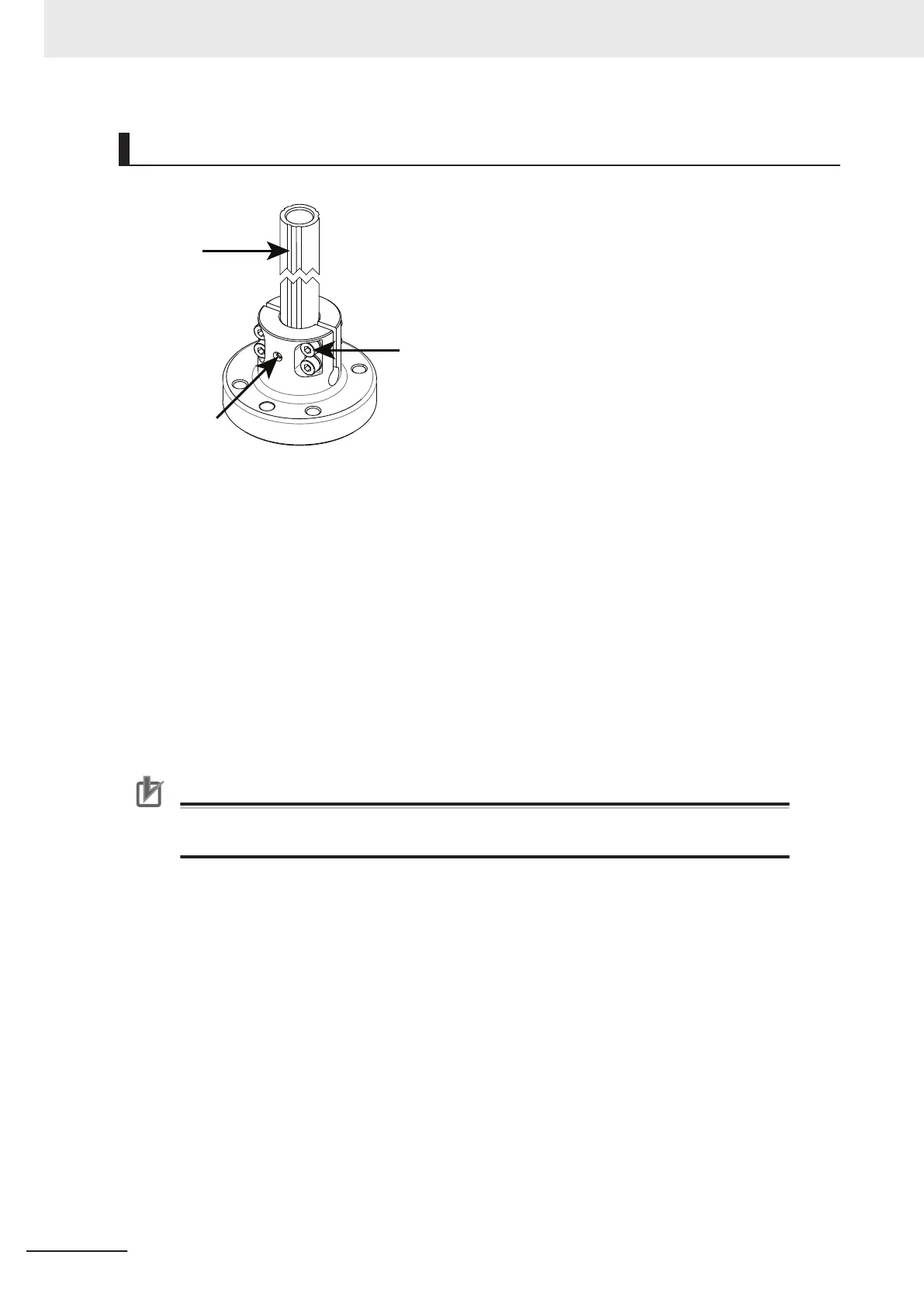
Quill Slots
Setscrew
Socket-head
Screws (x4)
1
Take note of the old tool flange position and orientation on the quill.
2 Loosen the setscrew and socket-head screws while holding the old tool flange in place. This
prevents it from falling off the z-axis quill.
3 Slide the tool flange off the z-axis quill.
4 Align the setscrew with the proper groove in the z-axis quill.
5 When the orientation is correct, slide the new tool flange up on the z-axis quill until it stops.
6 Apply thread lock (Loctite 243 or equivalent) to the setscrew and tighten to a torque of 1.1 N-m.
Precautions for Correct Use
Do not over-tighten the tool flange setscrew. This will cause off-center alignment of the
tool flange on the quill.
7
Apply thread lock (Loctite 222MS or equivalent) to the socket-head screws and then use a tor-
que wrench to tighten one of the socket-head screws to 1 N-m. Then, apply the same torque to
the other socket-head screws. Finally, tighten each socket-head screw to the full 2.5 N-m tor-
que.
8 When all socket-head screws are tight and the new tool flange is verified to be in the correct
orientation, the replacement procedure is complete.
6 Maintenance
6-10
i4L Robots User's Manual (I658)