EasyManuals Logo
Home>Omron>Measuring Instruments>K3HB-R

Omron K3HB-R User Manual

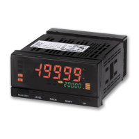
Omron K3HB-R
147 pages
To Next Page IconTo Next Page
To Previous Page IconTo Previous Page
Page #129 background imageLoading...
Page #129 background image
11-2
Features Section 1-1
BCD
Communications
1-1 Features
1-1-1 Overview
Measurement values (display values) output from Digital Indicators with a
BCD output can be read by devices such as a PLC, a large sized display
device (e.g., the M7E), or other devices.
1-1-2 Connection Example
PLC Connection
M7E Connection Example
Digital Indicator
Internal circuit
Programmable Controller (SYSMAC)
DC Input Unit
1.COMMON
Connector pin No. *
COM
IN
IN
IN
IN
IN
IN
OUT
OUT
COM
24 VDC
(0 V)
2.1
3.2
4.4
5.8
23.DATA VALID
24.RUN
25.COMMON
26.REQUEST
30.RESET
31.POLARITY
(Polarity: +, )
10°
240
240
240
240
+5 V
+24 V
0 V
Transistor Output Unit
Internal circuit
Internal circuit
DC power
supply
To 10
2
M7E Di
g
ital Dis
p
la
y
Unit
V
O
SEC
Digital Indicator
1.COMMON
Connector pin No. *
2.1
3.2
4.4
5.8
23.DATA VALID
24.RUN
25.COMMON
26.REQUEST
30.RESET
M7E-01D@N2, 01H@N2
31.POLARITY
(Polarity: +, )
10°
To 10
1
240
240
240
240
+5 V
V
O
D
C
B
A
DP
LE
8
V
O
D
C
B
A
DP
LE
8
V
O
D
C
B
A
DP
LE
8
Short circuit

Table of Contents

Other manuals for Omron K3HB-R

Questions and Answers:

Question and Answer IconNeed help?

Do you have a question about the Omron K3HB-R and is the answer not in the manual?

Omron K3HB-R Specifications

General IconGeneral
BrandOmron
ModelK3HB-R
CategoryMeasuring Instruments
LanguageEnglish

Related product manuals