4-2
Introduction Section 2-1
Operating
Procedures
2-1 Introduction
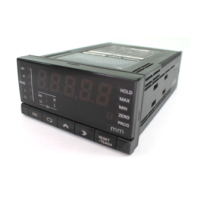
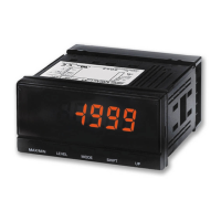
Use the procedures in the following sections to prepare the K3HB-DRT Digital
Indicators for use. Refer to the following reference pages/sections provided for
detailed information on each step.
2-1-1 Setup Procedure
2-1-2 Startup Procedure
Prepare the master, DeviceNet communications power supply, and Configura-
tor that will be used in the system. Use the Configurator to allocate Digital
Indicator data in the IN and OUT Areas. Refer to the DeviceNet Operation
Manual (W267) for information on related connection devices.
Note Up to 30 items can be allocated in the IN Area and up to 15 items can be allo-
cated in the OUT Area for remote I/O communications. To read and write
larger amounts of data, use explicit messages. Use explicit messages also for
reading and writing data only when required.
Step Item Details Reference
1 Mount the Digital Indicator. Mount the Digital Indicator to the panel. page 5-2
2 Wire the Digital Indicator. Wire the temperature inputs and comparative outputs to the
Digital Indicator terminals.
Note Do not turn ON the power supply to the peripheral
devices at this time.
---
3 Turn ON the power to the Digital Indi-
cator.
Turn ON the power connected to the Digital Indicator.
Note The Digital Indicator will start.
---
4 Set the DeviceNet node address. Set the DeviceNet node address (0 to 63) for the Digital Indi-
cator on the front panel. Set a unique node address for each
slave connected to the same master.
page 4-3
5 Turn OFF the power to the Digital
Indicator.
Turn OFF the power connected to the Digital Indicator. ---
Step Item Details Reference
6 Connect the DeviceNet com-
munications connector.
Connect the DeviceNet communications connector.
Note Do not turn ON the communications power supply at
this time. This power supply is also used as the inter-
nal circuit power supply for DeviceNet communica-
tions.
page 5-4
7 Turn ON the power to the Digi-
tal Indicator.
Turn ON the power connected to the Digital Indicator.
Note The Digital Indicator will start.
---
8 Turn ON the DeviceNet com-
munications power (V+, V
−).
Turn ON the communications power supply to DeviceNet.
Note The DeviceNet communications will start.
---
9 Check the MS/NS indicators Check that the status of the MS and NS indicators is as fol-
lows:
MS: Operating normally when lit green.
NS: Operating normally when lit green.
(DeviceNet online or communications connected.)
page 5-3

 Loading...