11-11
Programming Example 2: Connecting to a PLC Section 1-6
BCD
Communications
Note (1) I/O allocations marked with an asterisk are not used in this programming
example.
(2) The pin numbers shown in the above table are the pin numbers of the D-
sub connector on the special BCD output cable (sold separately).
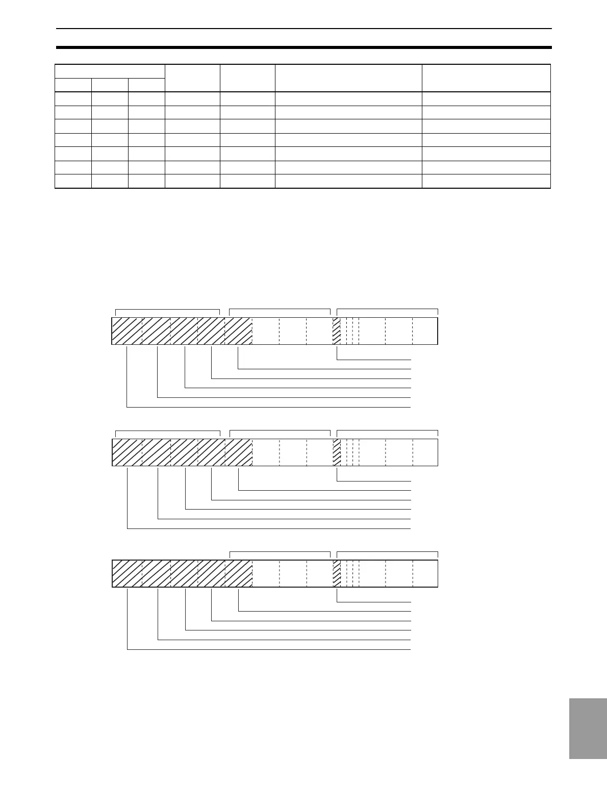
1-6-2 DM (Data Memory) Area
Read data is stored in the memory, as shown below.
1-6-3 Operation
In this programming example, IR 00113 in the CPU Unit of the PLC is turned
ON to read the measurement value of the three Digital Indicators (A, B and C)
to the PLC and store them in the DM area. No matter how long IR 00113
remains ON, data is sampled only once for each of Digital Indicators A, B and
C.
29 --- --- HOLD Input HOLD input A Output Unit, IR 0210*
--- 29 --- HOLD Input HOLD input B Output Unit, IR 0211*
--- --- 29 HOLD Output HOLD input C
30 --- --- RESET Input RESET input A Output Unit, IR 0212*
--- 30 --- RESET Input RESET input B Output Unit, IR 0213*
--- --- 30 RESET Input RESET input C Output Unit, IR 0214*
31 31 31 POL Output Data polarity signal Output Unit, IR 0107
Pin number Signal
name
Signal
direction
Meaning I/O allocation
DPM-A DPM-B DPM-C
IR 000
Polarity (bit 00)
10
4
digit (bits 00 to 03)
10
3
digit (bits 12 to 15)
10
2
digit (bits 08 to 11)
10
1
digit (bits 04 to 07)
10
0
digit (bits 00 to 03)
IR 001
IR 002
DPM-A data
IR 010
Polarity (bits 00)
10
4
digit (bits 00 to 03)
10
3
digit (bits 12 to 15)
10
2
digit (bits 08 to 11)
10
1
digit (bits 04 to 07)
10
0
digit (bits 00 to 03)
IR 011
IR 012
DPM-B data
IR 020
Polarity (bit 00)
10
4
digit (bits 00 to 03)
10
3
digit (bits 12 to 15)
10
2
digit (bits 08 to 11)
10
1
digit (bits 04 to 07)
10
0
digit (bits 00 to 03)
IR 021
IR 022
DPM-C data

 Loading...