11-10
Programming Example 2: Connecting to a PLC Section 1-6
BCD
Communications
1-6 Programming Example 2: Connecting to a PLC
The following programming example shows three Digital Indicators connected
to the SYSMAC C500 (OMRON).
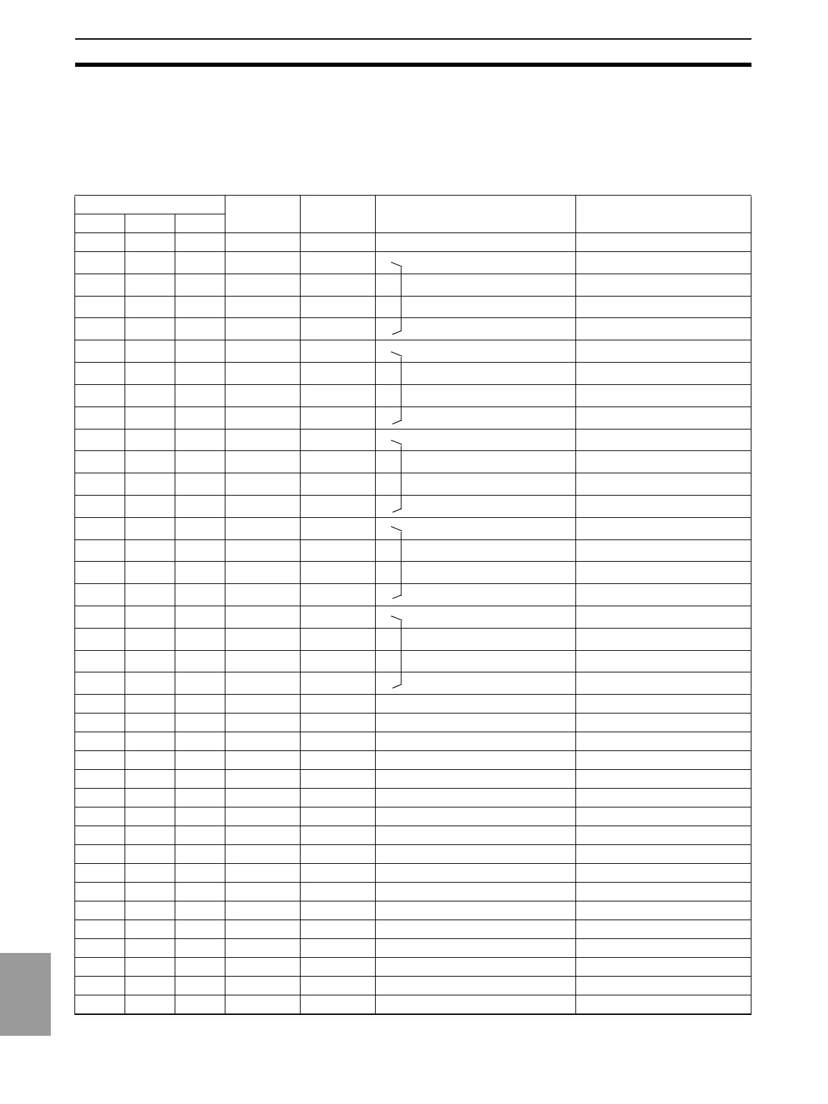
1-6-1 I/O Allocations
Pin number Signal
name
Signal
direction
Meaning I/O allocation
DPM-A DPM-B DPM-C
111COM GND: V0 Input Unit, IR 0000
222RD1-1Output
1 Read data 10
0
digit
Input Unit, IR 0001
333RD1-2Output
2 Read data 10
0
digit
Input Unit, IR 0002
444RD1-4Output
4 Read data 10
0
digit
Input Unit, IR 0003
555RD1-8Output
8 Read data 10
0
digit
Input Unit, IR 0004
666RD2-1Output
1 Read data 10
1
digit
Input Unit, IR 0005
777RD2-2Output
2 Read data 10
1
digit
Input Unit, IR 0006
888RD2-4Output
4 Read data 10
1
digit
Input Unit, IR 0007
999RD2-8Output
8 Read data 10
1
digit
Input Unit, IR 0008
10* 10* 10* RD3-1 Output
1 Read data 10
2
digit
Input Unit, IR 0009
11* 11* 11* RD3-2 Output
2 Read data 10
2
digit
Input Unit, IR 0010
12* 12* 12* RD3-4 Output
4 Read data 10
2
digit
Input Unit, IR 0011
13* 13* 13* RD3-8 Output
8 Read data 10
2
digit
Input Unit, IR 0012
14* 14* 14* RD4-1 Output
1 Read data 10
3
digit
Input Unit, IR 0013
15* 15* 15* RD4-2 Output
2 Read data 10
3
digit
Input Unit, IR 0014
16* 16* 16* RD4-4 Output
4 Read data 10
3
digit
Input Unit, IR 0015
17* 17* 17* RD4-8 Output
8 Read data 10
3
digit
Input Unit, IR 0100
18* 18* 18* RD5-1 Output
1 Read data 10
4
digit
Input Unit, IR 0101
19* 19* 19* RD5-2 Output
2 Read data 10
4
digit
Input Unit ,IR 0102
20* 20* 20* RD5-4 Output
4 Read data 10
4
digit
Input Unit, IR 0103
21* 21* 21* RD5-8 Output
8 Read data 10
4
digit
Input Unit, IR 0104*
22* 22* 22* OVER Output Data overflow, data underflow Input Unit, IR 0105
23* --- --- D·V Output Data valid signal A Input Unit, IR 0106
24* --- --- RUN Output RUN signal A Input Unit, IR 0109
--- 23 --- D·V Output Data valid signal B Input Unit, IR 0110
--- 24 --- RUN Output RUN signal B Input Unit, IR 0111
--- --- 23 D·V Output Data valid signal C Input Unit, IR 0112
--- --- 24 RUN Output RUN signal C
25 25 25 COM GND: V0 Output Unit, IR 0200
26 --- --- REQ Input PV output request A Output Unit, IR 0201
--- 26 --- REQ Input PV output REQUEST B Output Unit, IR 0202
--- --- 26 REQ Input PV output REQUEST C Output Unit, IR 0203*
27 --- --- MAX Input Peak value output REQUEST A Output Unit, IR 0204*
--- 27 --- MAX Input Peak value output REQUEST B Output Unit, IR 0205*
--- --- 27 MAX Input Peak value output REQUEST C Output Unit, IR 0206*
28 --- --- MIN Input Peak value output REQUEST A Output Unit, IR 0207*
--- 28 --- MIN Input Peak value output REQUEST B Output Unit, IR 0208*
--- --- 28 MIN Input Peak value output REQUEST C Output Unit, IR 0209*

 Loading...