11-7
Precautions for BCD Programming Section 1-4
BCD
Communications
1-3-3 Operating Method
Setting with front keys is not required for models with a BCD output.
1-4 Precautions for BCD Programming
1,2,3... 1. With models with a BCD output, only the measurement value, maximum
value, or minimum value can be read out.
2. The "+" and "
−" polarity correspond to low and high of the POL signal.
3. Read data while the D.V. is ON.
4. Data cannot be written from the PLC to the Digital Indicator.
1-5 Programming Example 1: Connecting to a PLC
The following programming example shows a single Digital Indicator con-
nected to the SYSMAC C500 (OMRON).
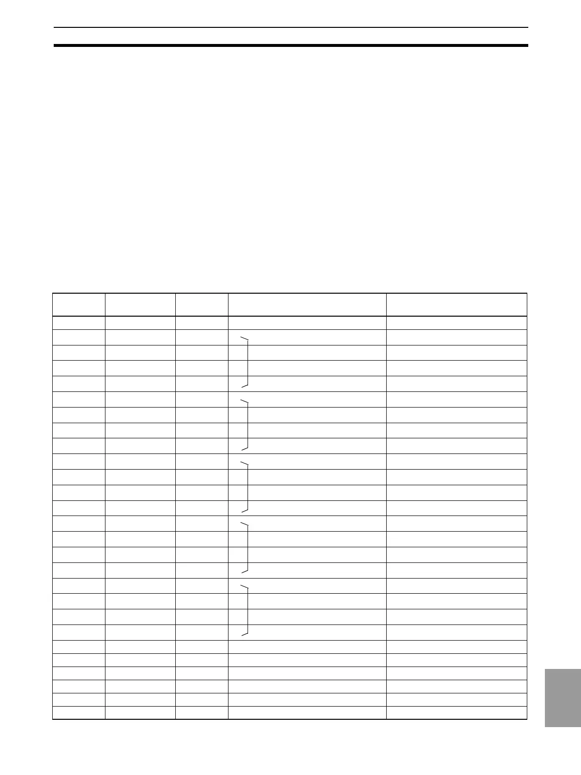
1-5-1 I/O Allocations
Pin
number
Signal name Signal
direction
Meaning I/O allocation
1 COM GND: V0*
2 RD1-1 Output
1 Read data 10
0
digit
Input Unit, IR 0000
3 RD1-2 Output
2 Read data 10
0
digit
Input Unit, IR 0001
4 RD1-4 Output
4 Read data 10
0
digit
Input Unit, IR 0002
5 RD1-8 Output
8 Read data 10
0
digit
Input Unit, IR 0003
6 RD2-1 Output
1 Read data 10
1
digit
Input Unit, IR 0004
7 RD2-2 Output
2 Read data 10
1
digit
Input Unit, IR 0005
8 RD2-4 Output
4 Read data 10
1
digit
Input Unit, IR 0006
9 RD2-8 Output
8 Read data 10
1
digit
Input Unit, IR 0007
10* RD3-1 Output
1 Read data 10
2
digit
Input Unit, IR 0008
11* RD3-2 Output
2 Read data 10
2
digit
Input Unit, IR 0009
12* RD3-4 Output
4 Read data 10
2
digit
Input Unit, IR 0010
13* RD3-8 Output
8 Read data 10
2
digit
Input Unit, IR 0011
14* RD4-1 Output
1 Read data 10
3
digit
Input Unit, IR 0012
15* RD4-2 Output
2 Read data 10
3
digit
Input Unit, IR 0013
16* RD4-4 Output
4 Read data 10
3
digit
Input Unit, IR 0014
17* RD4-8 Output
8 Read data 10
3
digit
Input Unit, IR 0015
18* RD5-1 Output
1 Read data 10
4
digit
Input Unit, IR 0100
19* RD5-2 Output
2 Read data 10
4
digit
Input Unit, IR 0101
20* RD5-4 Output
4 Read data 10
4
digit
Input Unit, IR 0102
21* RD5-8 Output
8 Read data 10
4
digit
Input Unit, IR 0103
22* OVER Output Data overflow, data underflow Input Unit, IR 0104*
23* D·V Output Data valid signal Input Unit, IR 0105
24* RUN Output RUN signal Input Unit, IR 0106
25* COM GND: V0*
26* REQ Input Measurement value output request Output Unit, IR 0200
27* MAX Input Maximum value output request Output Unit, IR 0201*

 Loading...