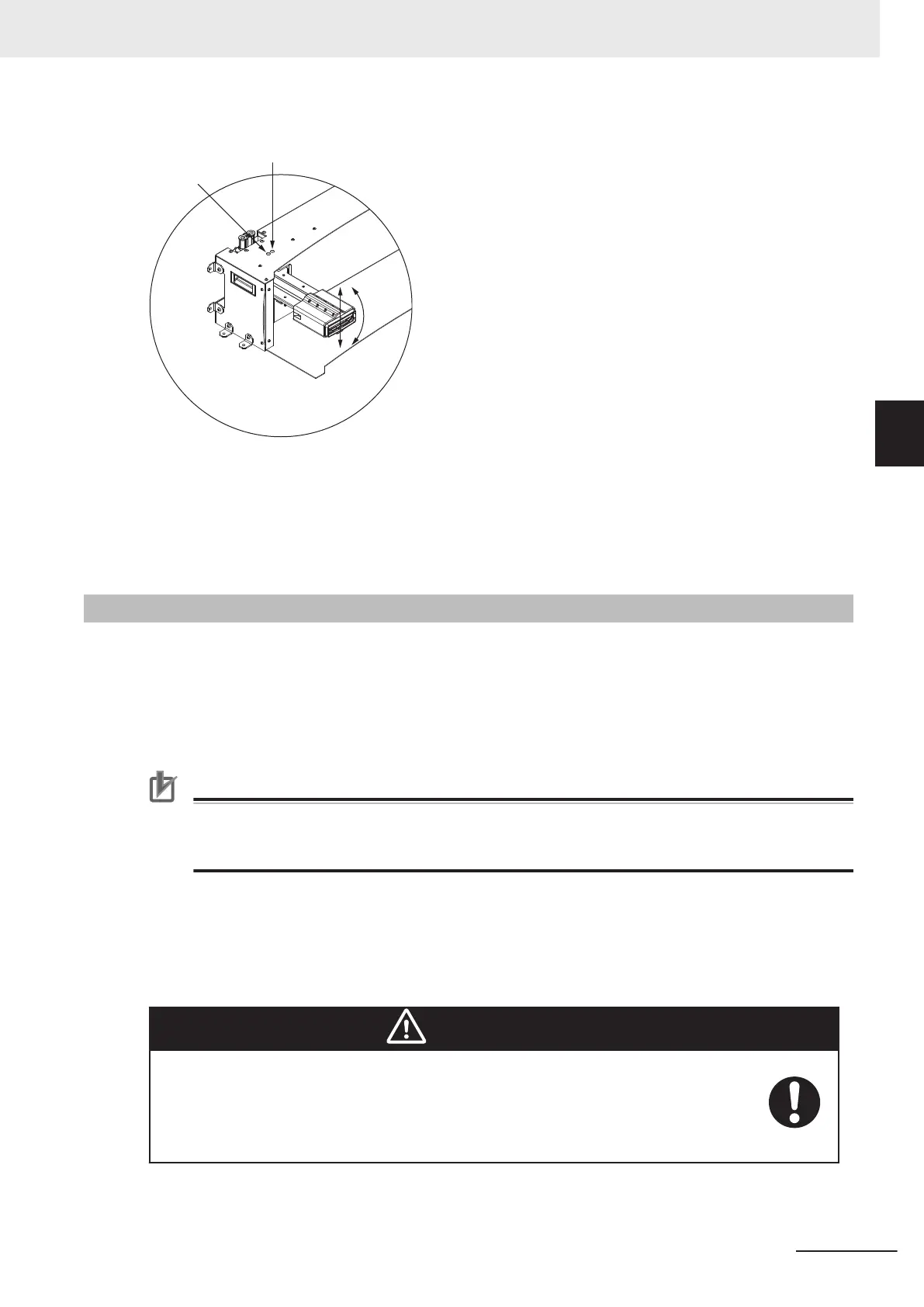
Vertical
Height
Adjustment
Angle
Adjustment
Use a 6 mm hex key to adjust the charging paddle in the following manner.
• Turn the vertical height adjustment screw clockwise to increase the height of the charging paddle
and counterclockwise to decrease the height of the charging paddle.
• Turn the angle adjustment screw clockwise to lower the angle and counterclockwise to raise the an-
gle of the charging paddle.
3-2-4
Electrical Connections
The Power Supply Box is permanently connected equipment. The user must supply the power cord
from the facility to the electrical access panel on the side of the unit.
The user must punch a hole through the electrical access panel and install a user-supplied strain relief
for the power cord. The strain relief attaching to the electrical access panel must be sized appropriate-
ly for the user-supplied power cord.
Precautions for Correct Use
The Main Disconnect Switch located on the electrical access panel controls current flow into the
Power Supply Box. When the switch is in the horizontal position, it is OFF and when it is in the
vertical position, it is ON.
The Power Supply Box input power is protected by 25 A rated circuit breakers.
When connecting the power cord to its mating connector on the Docking Target, ensure that the power
cord connector is seated completely and secured. The power cord must be placed behind the Docking
Target. It must be properly protected and must not pose any hazards to personnel or interfere with oth-
er equipment.
WARNING
• Charging Station strain reliefs and the power cords must be installed by a licensed
or appropriately certified electrician.
• If power cords lie on the ground, you must make sure that they are highly visible to
prevent tripping hazards and must be protected from physical damage with barriers
or covers.
3 Installation
3-7
AMR (Autonomous Mobile Robot) MD-series Platform User's Manual (I681)
3-2 Charging Station Installation
3
3-2-4 Electrical Connections
 Loading...