3-12
Maintenance Port Extension Proce-
dure
Use the following procedure to extend access to the Maintenance Port.
A Maintenance Port Extension kit (73955-000) is required for this procedure. The kit contains the fol-
lowing items:
• Ethernet Passthrough connector
• Ethernet patch cable, 1 ft
• Two M3 screws and nuts
The following tools are required for this procedure:
• T10 star bit
• 5.5 mm wrench
1 Turn the AMR OFF.
2
Place the Main Disconnect Switch in the OFF position.
3
Remove the User Connections area cover to access the Connector Panel.
4
Remove the Right Skin. Refer to 6-11-1 Removing and Replacing Skins on page 6-17 for
more information.
5
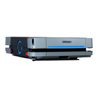
Locate the Maintenance Port extension hole on the AMR.
Maintenance Port
Extension Hole
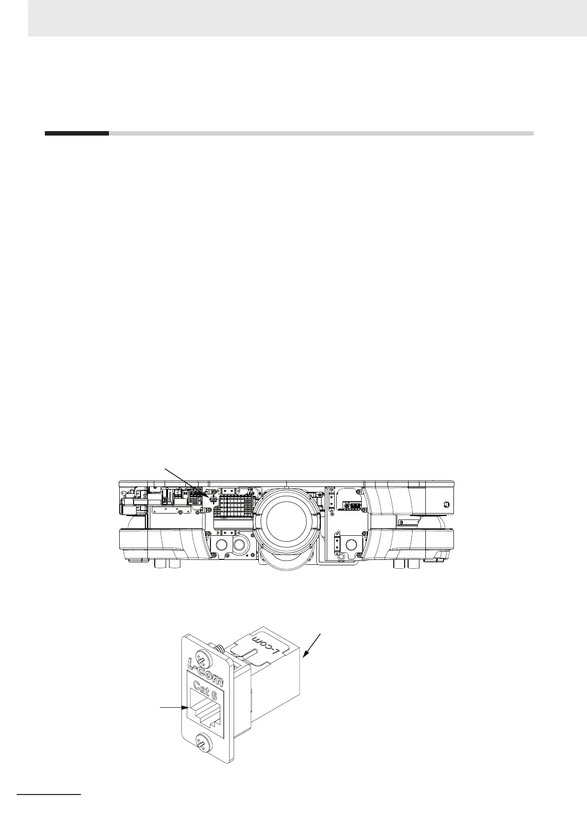
6 Install the Ethernet passthrough connector on the Maintenance Port extension hole using the
provided screws and nuts.
3 Installation
3-44
AMR (Autonomous Mobile Robot) MD-series Platform User's Manual (I681)
 Loading...