1-2-8
Payload Mounting Surface
Payloads are mounted directly to the top of the AMR chassis. Several mounting points are available
for various payload designs.
Mounting points are aligned with internal cross-members for payload support purposes.
1-2-9
Main Disconnect Switch
The Main Disconnect Switch completely removes all battery power from the AMR for maintenance or
other abnormal situations.
1-2-10
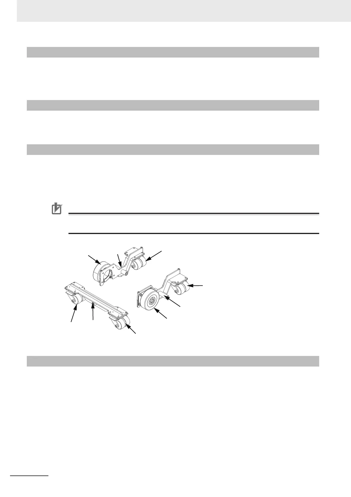
Drive Train and Suspension
The AMR utilizes a differential-type drive train with two drive-wheels. This drive train style makes the
AMR highly maneuverable and allows it to rotate in place. The drive wheels have for traction and dura-
bility. Casters are mounted to rocker arms and freely rotate 360° to provide stability during operation.
This arrangement allows the AMR to maintain contact with the floor over uneven areas or bumps.
Precautions for Correct Use
Replacement of the differential drive train, casters, and wheels require an OMRON service en-
gineer. Contact your local OMRON representative for more information.
Drive
Wheel
Rocker
Arm
Casters
Drive
Wheel
Casters
Casters
Rocker
Arm
Rocker
Arm
Casters
1-2-11
AMR Controller
The AMR Controller is the AMR's main computing system that provides all navigational controls and
application interfaces. The AMR Controller consists of two main components: the Base Layer contain-
ing standard PC interfaces and the Mobile Robot Layer for the processing of the AMR control interfa-
ces and network interface.
The AMR Controller runs the SetNetGo operating system and the Advanced Robotics Automation
Management (ARAM) software. It also runs a variant of the Mobile Autonomous Robot Controller (PO-
LO). The AMR Controller is housed inside the electronics bay as displayed in the following figure.
Refer to the AMR Controller User's Guide (Cat. No. I650) for more information.
1 Overview
1-12
AMR (Autonomous Mobile Robot) MD-series Platform User's Manual (I681)
 Loading...