1-9
Coordinate System
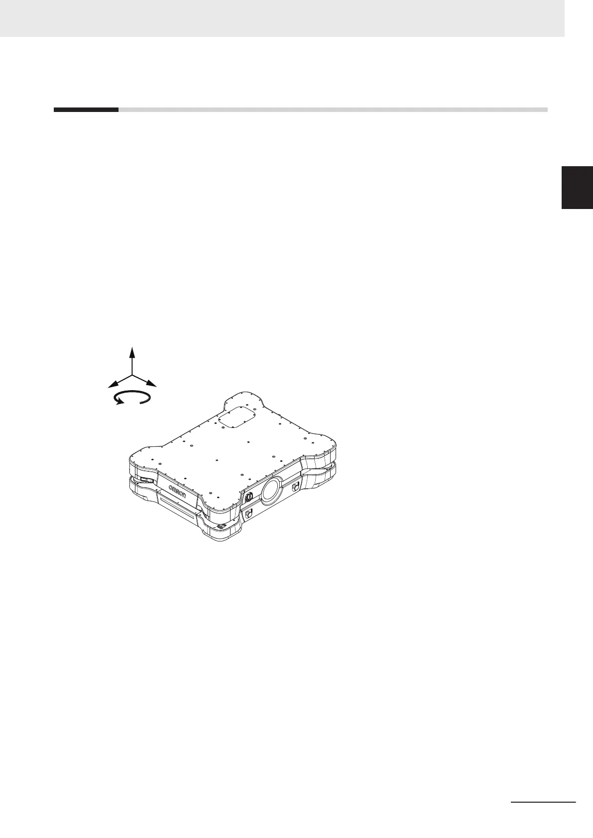
AMRs use the X, Y, Z, and Theta coordinate system displayed in the figure below. This information is
relevant for some of the procedures used in this manual, such as identifying which are the left or right
sides of the AMR. For example, the AMR Controller is located near the rear of the AMR, and the +X
direction is the direction of AMR forward travel.
The origin of the AMR coordinate system is the ideal point on the floor exactly half way between the
center of the two drive wheels. The origin of the coordinate system is the AMR's center of rotation.
Coordinates are required for procedures such as installing and configuring options such as lasers, and
also for understanding the center of gravity envelope. The AMR's coordinates are also associated with
the map coordinates.
The rotation value Theta specifies the AMR's angle of rotation, which determines its heading or direc-
tion of travel.
The origin of the vertical coordinate Z is set at ground level (Z=0). The value of Z is required when you
calculate the mount position of optional items such as Side Lasers. Positions of optional items like this
are set in MobilePlanner.
+X
+Y
+Z
Front
Rear
Left
Right
+θ
1 Overview
1-39
AMR (Autonomous Mobile Robot) MD-series Platform User's Manual (I681)
1-9 Coordinate System
1
 Loading...