5-1 Connecting to Host Via Ethernet
5-4
• Host Settings
The following settings must be set at the host.
Item Host Settings
Network number 1 to 127
Conversion table Node number: 1 to 254
IP address: 0.0.0.0 to 255.255.255.255
UDP port number 1 to 65535, default is 9600.
IP address 0.0.0.0 to 255.255.255.255
Subnet mask 0.0.0.0 to 255.255.255.255
Default gateway 0.0.0.0 to 255.255.255.255
IP proxy address “”(blank), 0.0.0.0 to 255.255.255.255
Node number 1 to 254
Routing tables Define communications paths for FINS messages. Routing tables are
set from the CX-Programmer.
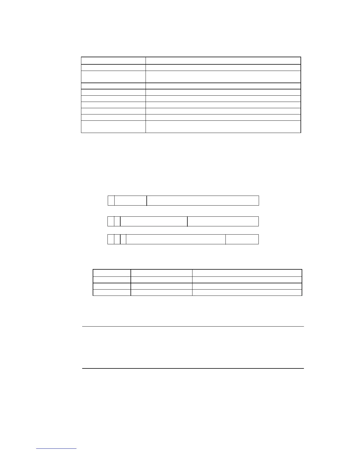
IP Address Configuration
The IP address is comprised of 32 bits of binary data, consisting of the net ID and host ID.
The net ID is the address that identifies the network, and the host ID is the ID that identifies
the host (node).
The IP address is divided into class A, B, and C. Select the address system from among the
classes according to the network configuration.
15
7
0 bits
0 bits
0 bits
31
31
Class A
Class
B
Class
C
Net ID (7 bits)
Host ID (24 bits)
23
31
Host ID (16 bits)Net ID (14 bits)
0
0
1
0
1
1
Net ID (21 bits)
Host ID (8 bits)
The number of networks and hosts that can be identified depends on the class used.
Class Number of networks Number of hosts
Class A Small
2
24
− 2 max. (16,777,214 max.)
Class B Medium
2
16
− 2 max. (65,534 max.)
Class C Large
2
8
− 2 max. (254 max.)
The IP address is a 32-bit value divided into four 8-bit fields. Each octet is expressed as a
decimal and is separated by a period.
Example: 10000010 00111010 00010001 00100000 → 130.58.17.32
Reference • Set the same net ID for all nodes in the same network.
• The net ID of the IP address is the value that identifies the Ethernet network (IP net-
work segment). The net ID is not the same as the network address used for FINS
communications.
•
The IP network segment is the logical network unit that is configured by the nodes that
have the same net ID.

 Loading...


