3-8 Installing the Controller Link Interface Unit
3-44
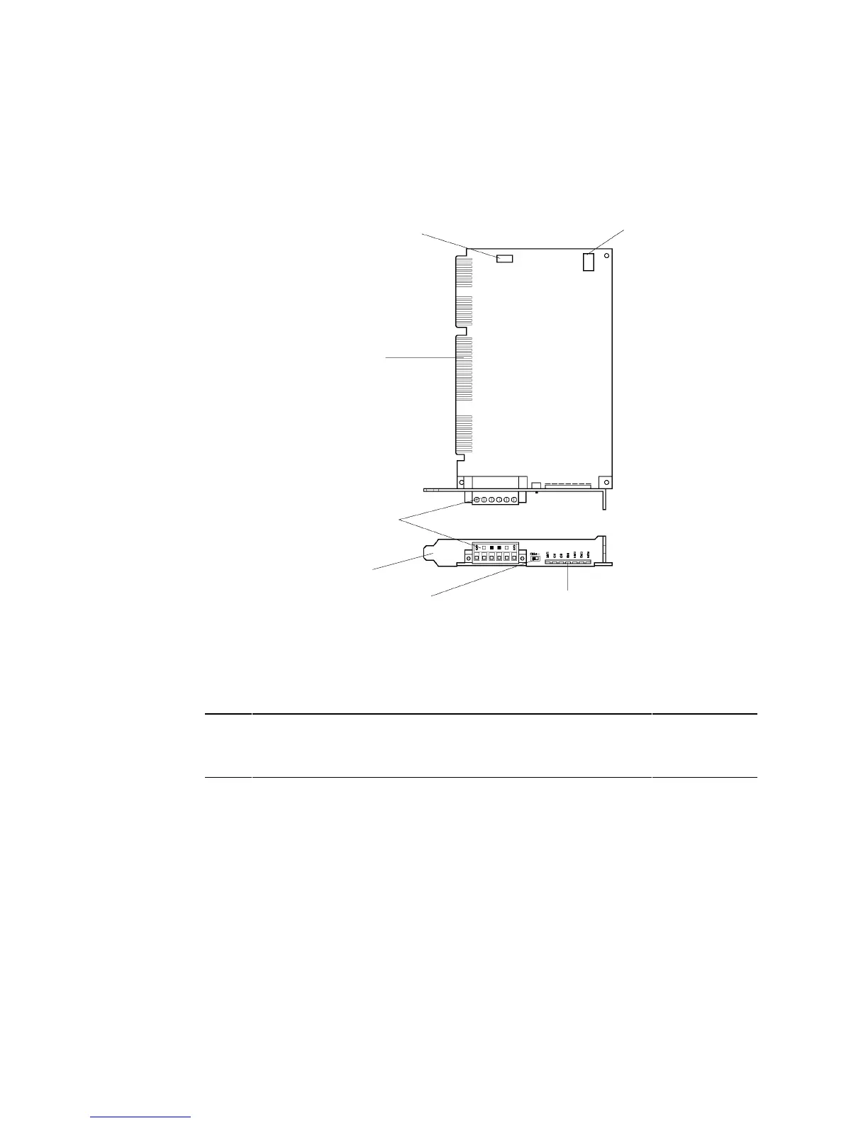
3-8-2 Nomenclature and Functions
Familiarize yourself with the nomenclature and functions of the Controller Link Support
Board before operation.
Card Edge Connector
Connects to the connector of
the Connector Conversion
Board.
Memory Allocation Switch
Set at the factory. Do not change
the factory setting.
Communications Connector
Connects to Controller Link Network
communications cable using the cable
connector provided
.
Interrupt shorting Pin
Set at the factory. Do not
change the factory setting.
Terminating Resistance Switch
This is a slide switch. Turn ON the
terminating resistance if the Board is
at the end node in a Controller Link
Network. The switch must be set to
OFF at other nodes.
Indicators
Display the status of the
Board and Network.
Plate
Attaches to the cover.
Reference To identify nonconforming Controller Link Boards, check the Model printed on the Plate.
This will tell you whether it conforms with EC Directives.
Model 3G8F5-CLK21: Does not conform with EC Directives
Model NS-CLK01: Conforms with EC Directives

 Loading...


