Appendix 3 Using NS-AL002 Converters
A-24
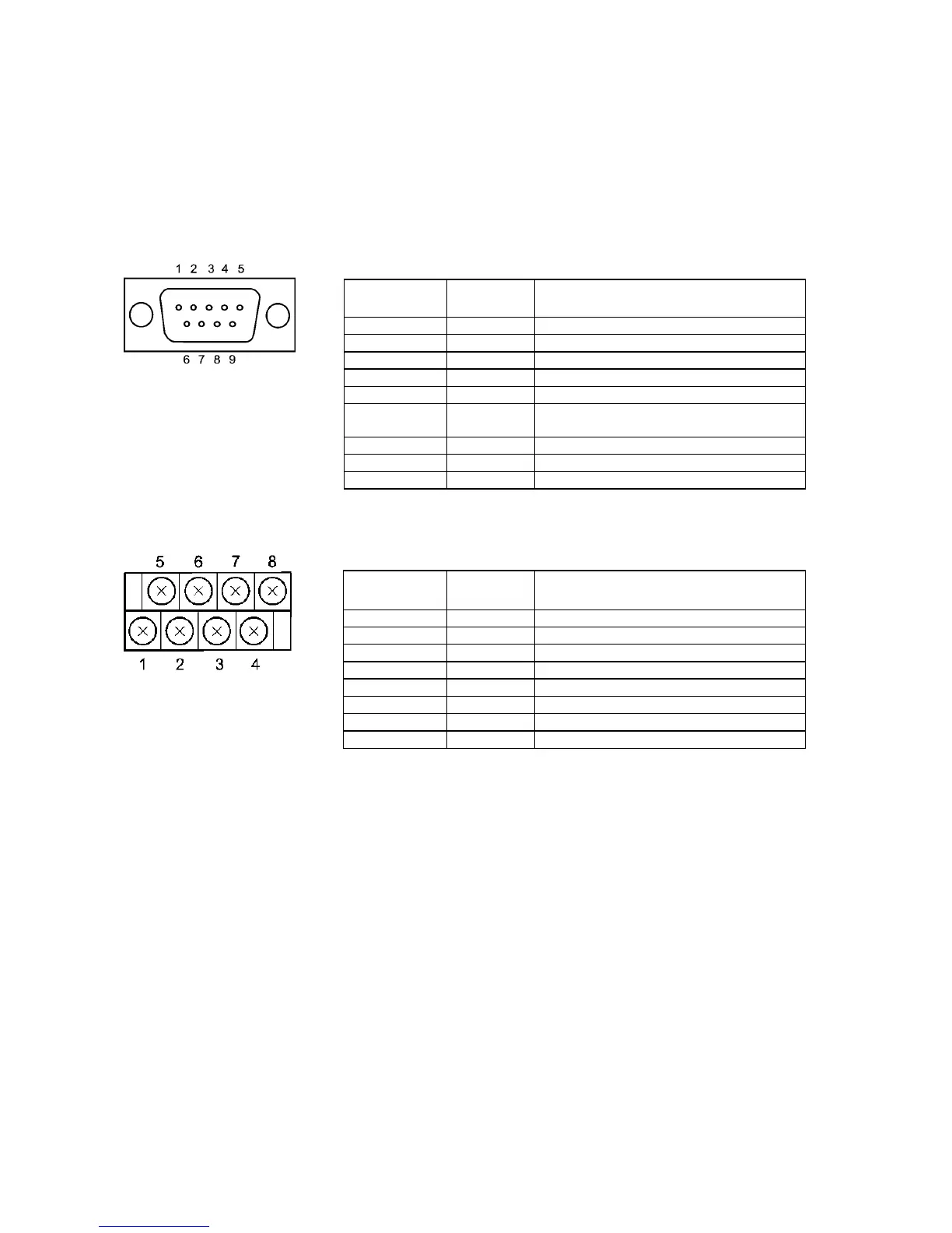
A-3-5 Pin Arrangement
The Adapter has a connector for RS-232C interface connection and a terminal block for
RS-422A/485 interface connection.
The pin arrangements for the RS-232C connector and RS-422A/485 terminal block are as
follows:
RS-232C Connector
Terminal block
pin number
Signal name Signal direction
Adapter ⇔ PT
1 NC
2 RD
←
3 SD
→
4 CS
← (RS signal short-circuited internally)
5 RS
→
6 5 V
(30 mA max.)
←
7 or 8 NC (Pins 7 and 8 are short-circuited.)
9 SG
−
Connector hood FG Connects to functional ground terminal of PT.
RS-422A Terminal Block
Terminal block
pin number
Signal name
Signal direction
Adapter ⇔ Host
1 FG Connects to functional ground terminal of PT.
2 RDB (+)
←
3 SDB (+)
→
4 RSB (+)
→
5 NC ---
6
RDA (−) ←
7
SDA (−) →
8
RSA (−) →

 Loading...


