5-2 Connecting to the Host Using Controller Link
5-17
5-2 Connecting to the Host Using Controller Link
This section explains the method for connecting to the host using a Controller Link Interface
Unit.
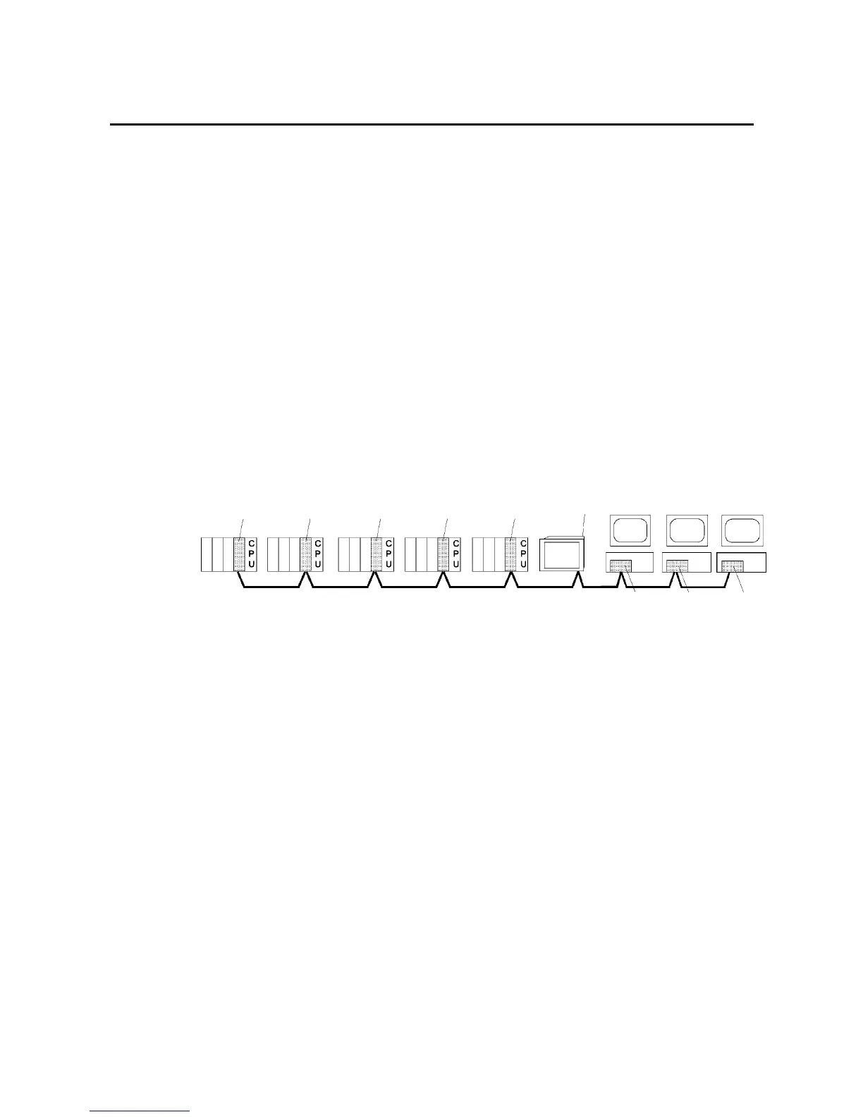
5-2-1 What Is a Controller Link Network?
A Controller Link Network is an FA Network that can send and receive large data packets
flexibly and easily among the OMRON C200HX/HG/HE PLC Programmable Terminal (PTs),
SYSMAC CS-series PLCs, CJ-series PLCs, CQM1H-series PLCs, C200HX/HG/HE PLCs,
CVM1/CV-series PLCs, IBM PC/AT or compatible computers, and NS-series PTs. The Con-
troller Link supports data links that enable data sharing and a message service that enables
sending data and receiving data when required. Data link areas can be freely set to create a
flexible data link system and effectively use data areas.
The network is connected using shielded twisted-pair cable or optical fiber cable. In addition,
the Controller Link Network can transfer large quantities of data at high speed, so that it is
possible to construct a wide-area network easily that supports from low-level systems to high.
For details on data links and message service, refer to the Controller Link Support Board
Operation Manual (W307), Controller Link Support Board for PCI Bus Operation Manual (Cat.
No. W383), and the Controller Link Unit Operation Manual (Cat. No. W309).
Note: An optical fiber cable is not available for NS-series PTs.
PLC, SYSMAC
CJ Series
CJ1W-CLK21
Controller Link Unit
PLC, SYSMAC
CQM1H Series
CQ1H-CLK21
Controller Link Unit
PLC, SYSMAC
CS Series
CS1W-CLK21
Controller Link Unit
PLC, SYSMAC
C200HX/HG/HE
C200HW-CLK21
Controller Link Unit
PLC, SYSMAC
CVM1/CV Series
CVM1-CLK21
Controller
Link Unit
NS-CLK21
Controller Link
Interface Unit
IBM PC/AT or
compatible
FC98 personal
computer
Personal computer
3G8F5-CLK21
Controller Link
Support Board
3G8F6-CLK21
Controller Link
Support Board
3G8F7-CLK21
Controller Link
Support Board
NS Series
NS12-TS
@
NT10-TV
@
To connect the PT to the Controller Link, it is necessary to install a Controller Link Interface
Unit on the PT. A Controller Link Interface Unit can be used only for the NS15, NS12 and
NS10 NS-series PTs. Refer to 3-8 Installing the Controller Link Interface Unit for the proce-
dure for installing and wire the Controller Link Interface Unit.
When communicating by Controller Link, the network number, node number, routing tables,
and data link tables must be set. Use the CX-Designer to set the settings. For details, refer to
System Settings and Project Properties in the CX-Designer’s Online Help.
Required Devices
To construct a Controller Link Network, the devices described in the following table are re-
quired.

 Loading...


