3-8 Installing the Controller Link Interface Unit
3-43
3-8 Installing the Controller Link Interface Unit
This section describes the method for installing and wiring the Controller Link Interface Unit,
which can be mounted to an NS10, NS12, or NS15 PT. The Controller Link Interface Unit
cannot be mounted to an NS8 or NS5 PT.
3-8-1 Controller Link Interface Unit Components
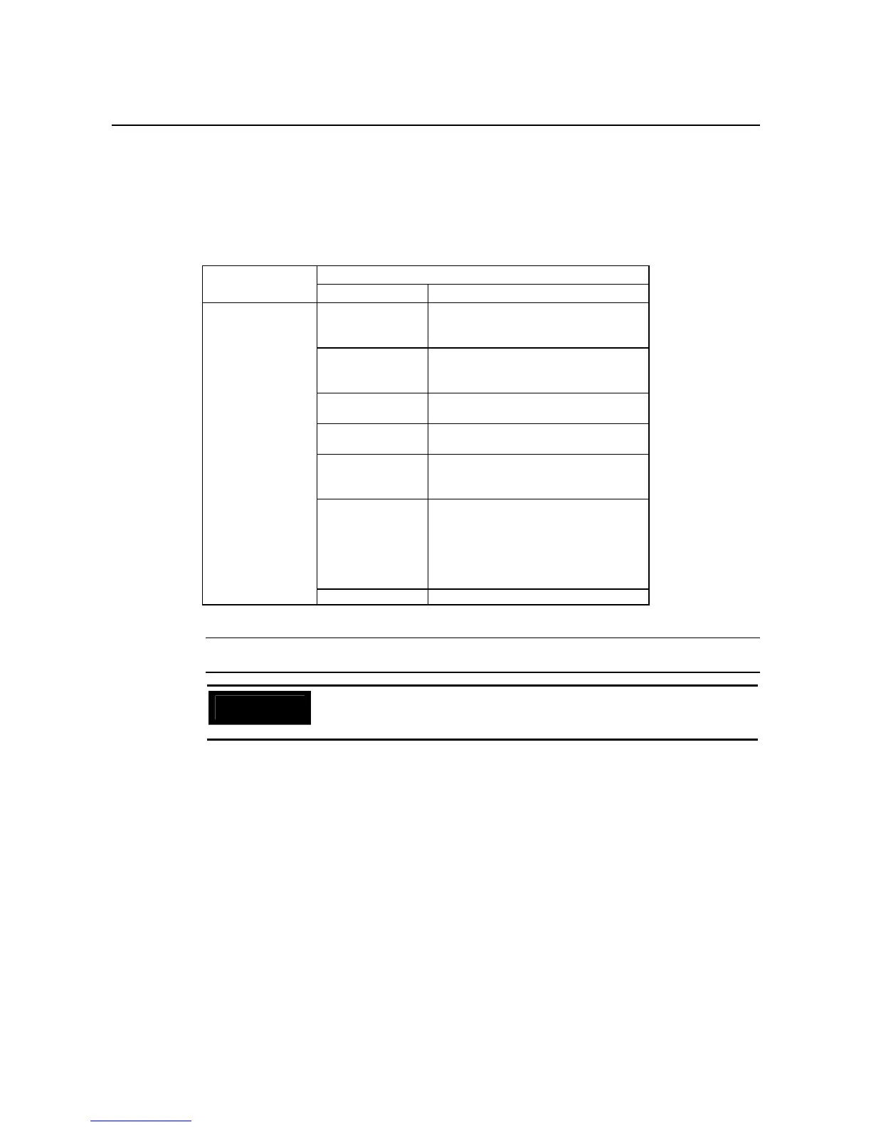
The following table shows the Controller Link Interface Unit’s product configuration.
Components
Model
Name Contents
NS-CLK21
Controller Link
Interface Unit
NS-CLK001 Con-
nector Conversion
Board (1)
Used for mounting the Controller Link
Support Board to the PT.
NS-CLK01 Con-
troller Link Sup-
port Board (1)
Connects the PT to the Controller Link
Network.
Connector (1) Connects the communications cable
and Controller Link Support Board.
Cover (1) Protects the connector and the Con-
troller Link Support Board.
Cable (1) Connects the cover and the PT’s func-
tional ground terminal to prevent
noise.
Screw (M3) (10) These screws are used for:
• Securing the Connector Conversion
Board to the back of the PT.
• Securing the cover to the back of
the PT.
• Attaching the cable to the cover.
Instruction sheet Instruction sheet for NS-CLK21
Reference
NS-CLK21 Units with lot number 12Y2 or later (manufactured on November 12, 2002
or later) comply with EC Directives.
Precautions
for Safe Use
To comply with EC Directives when mounting the Controller Link Interface Unit
on the PT, attach the PT to a control panel that has been cut to fit to size. (Refer
to 3-1-3 Mounting the PT to the Control Panel for cutout dimensions.)

 Loading...


