5-1 Connecting to Host Via Ethernet
5-15
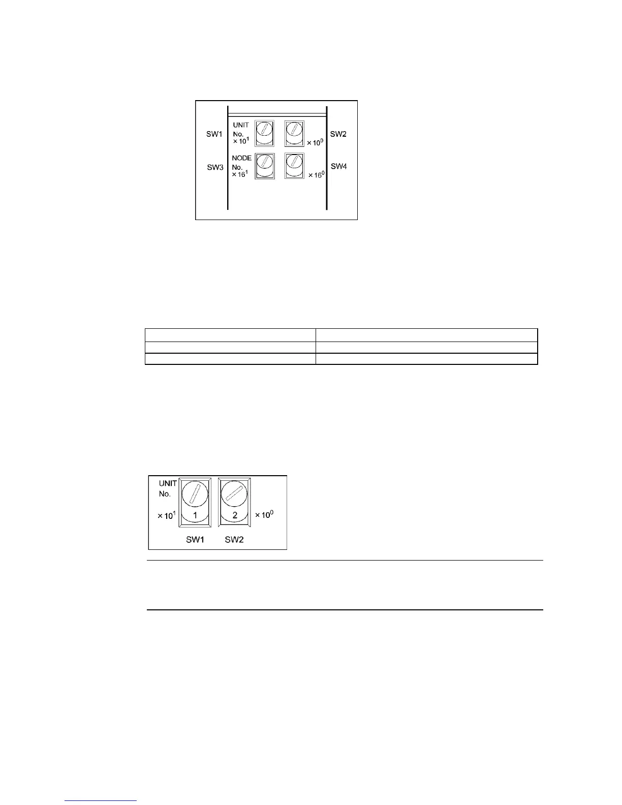
Switch Layout
The layout of the two switches is shown in the following diagram.
• Set the unit number using SW1 and SW2. Set the unit number so that it is different from
other CPU Bus Units in the system.
• Set the node number using SW3 and SW4.
Setting Range
Each switch can be set within the following range.
Settings Setting range
Unit number (SW1, SW2) 00 to 15 (decimal)
Node number (SW3, SW4) 01 to 7E hexadecimal (1 to 126 decimal)
Setting Unit Numbers
The unit number is used to identify each Unit when multiple CPU Bus Units are mounted to
the CPU Unit.
Use the left switch (SW1) to set the ten’s digit, and the right switch (SW2) to set the one’s
digit. Set between 00 and 15 decimal.
Setting Example
This example is for unit number 12.
Reference • The unit number cannot be set to a value more than 15. If the unit number is set to a
value higher than 15, the ERH indicator in the display will light.
• When more than one CPU Bus Unit is mounted to a single PLC, set each Unit with a
unique unit number.

 Loading...


