5-3 Connecting to Host via EtherNet/IP
5-28
NODE
NO.
16
1
16
0
Setting range
01 to 7E (1 to 126 decimal)
Set the upper digit using the left rotary switch and the lower digit using the right rotary switch.
The factory setting is 01.
When using automatic generation to convert addresses, set the node number to the same
value as that of the rightmost byte of the local IP address. If the same values cannot be set,
the IP address table method or combination method must be used to convert the addresses.
Setting Local IP Addresses
Set the local IP address with the CX-Programmer or other Support Software.
Refer to the EtherNet/IP Unit Operation Manual (Cat. No. Z909) for details on setting meth-
ods.
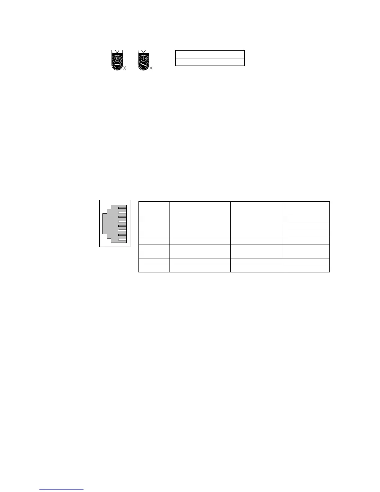
Ethernet Connectors
This is the connector used to connect the twisted-pair cable to the Ethernet.
• Electrical Characteristics: Conforms to IEEE802.3 standards.
• Connector Layout: RJ45 8-pin modular connector (conforms to ISO 8877).
Connec-
tor Pin
Signal name Abbreviation Signal direction
1 Send data TD+ Output
2
Send data
− TD−
Output
3 Receive data + RD+ Input
4 Not used.
− −
5 Not used.
− −
6
Receive data
− RD−
Input
7 Not used.
− −
8 Not used.
− −
1
8

 Loading...


