6 Installation
6 - 10
NX-series EtherNet/IP Coupler Unit User’s Manual (W536)
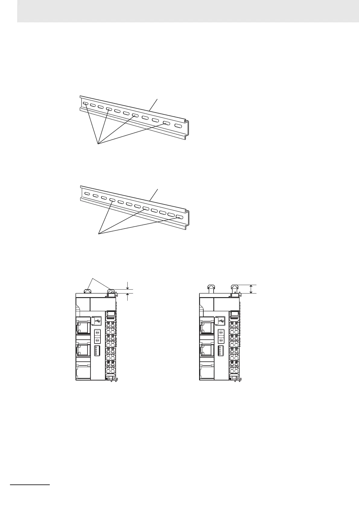
1 Install the DIN Track.
• Using a PFP-50N/100N DIN Track
Use one M4 screw for each three holes in the DIN Track. Ensure the head of each screw is at
least 2 mm below the top of the DIN Track to prevent damage to units. There must be a screw
for each interval of 105 mm or less. The screw tightening torque is 1.2 N·m.
• Using an NS 35/7,5 PERF or NS 35/15 PERF DIN Track
Use one M6 screw for each four holes in the DIN Track. There must be a screw for each interval
of 100 mm or less. The screw tightening torque is 5.2 N·m.
2
Make sure that the two DIN Track mounting hooks on the EtherNet/IP Coupler Unit are in the locked
position.
If the DIN Track mounting hooks are pressed down, they are in the locked position.
If the DIN Track mounting hooks are up, they are in the unlocked position.
If the DIN Track mounting hooks are unlocked, press them down into the locked position.
DIN Track
Use one screw for each three holes.
DIN Track
Use one screw for each four holes.
DIN Track
mounting hooks
4.5 mm
9.5 mm
DIN Track Mounting
Hooks in Locked Position
DIN Track Mounting
Hooks in Unlocked Position

 Loading...


