4-39
CHAPTER 4 Adjustment
(2) Setting the Z-axis soft limits
Make this setting from outside the safeguard enclosure.
The Z-axis has mechanical stoppers xed at the upper and lower ends of
the Z-axis movement range. When the actual working range of the robot is
smaller than the maximum working envelope or the manipulator interferes
with the peripheral equipment, reduce the Z-axis plus (+) soft limit [pulses]
to narrow the working envelope.
(3) Setting the R-axis soft limit
To make this setting, set emergency stop just as for the X-axis and Y-axis,
or be sure to do this from outside the safeguard enclosure. The R-axis has
no mechanical stoppers. When the actual working range of the R-axis is
small or it interferes with the peripheral equipment, reduce the R axis plus
(+) soft limit [pulse] and minus (-) soft limit [pulses] to narrow the working
envelope.
(4) Relation between the X, Y and R-axis movement angle, the Z-axis move-
ment distance and the number of pulses
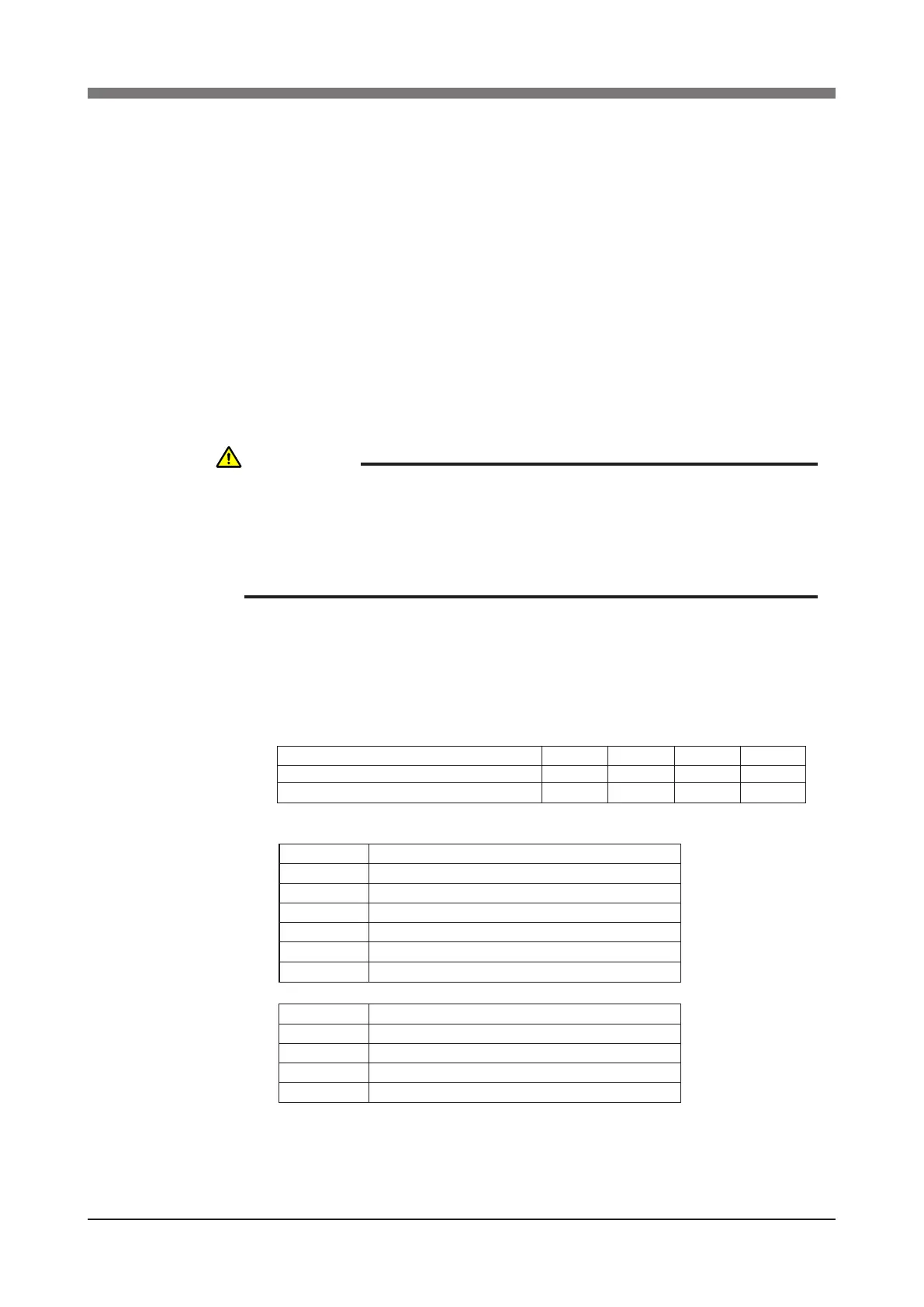
The tables below are for calculating resolver pulses with respect to the X, Y
and R-axis movement angles and to the Z-axis movement distance for each
robot. Use these gures as a guide to set the soft limits.
X, Y and R-axis speed reduction ratio and Z-axis ball screw lead for each robot
Operation angle/distance vs. number of resolver pulses
Z-axis
X, Y and R-axis speed reduction ratio
Robot model
R6YXH250, R6YXH350, R6YXH400
R6YXX1200
X-axis
50
121
Y-axis
50
105
Z-axis
12mm
10mm
R-axis
50
50
Lead
10mm
12mm
20mm
30mm
Number of resolver pulses per lead movement
16384
16384
16384
16384
Speed ratio
30
50
80
100
105
121
Number of resolver pulses per turn (360 degrees)
491520
819200
1310720
1638400
1720320
1982464
CAUTION
OVERLOADS MAY OCCUR IF THE SOFT LIMIT IS ALMOST NEAR THE
ENCODER PULSE AT THE MECHANICAL STOPPER AND THE
OPERATING POINT IS USED AT THE EDGE OF THE MOVEMENT RANGE.
SET THE SOFT LIMIT TO THE INNER SIDE OF THE MECHANICAL
STOPPER WITH AN AMPLE SAFETY MARGIN.
 Loading...


