2.5 Install all the ceramic capacitors
80 / 60 / 40 / 30 / 20m version: Install all 16 through-hole capacitors in accordance with the
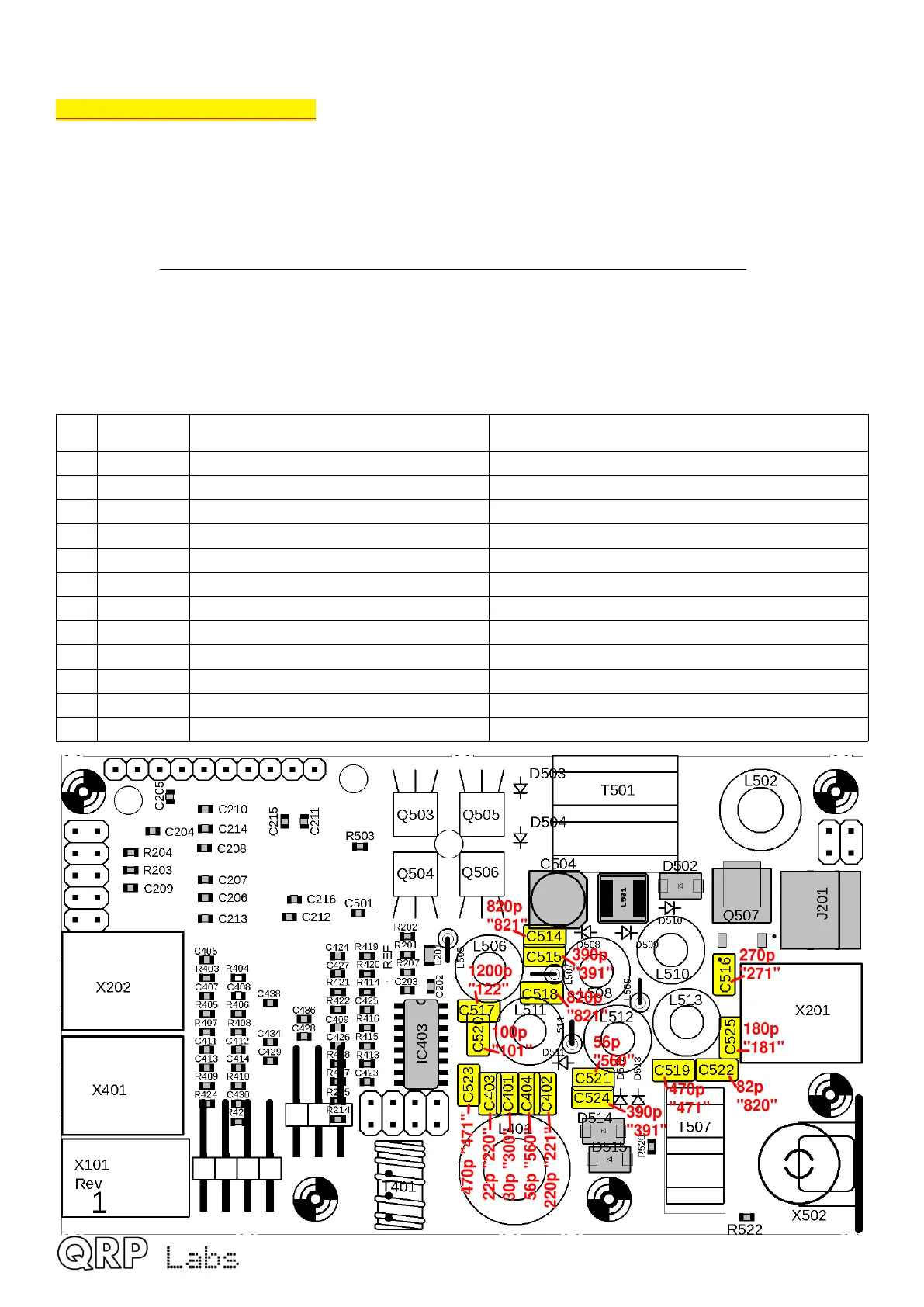
following diagram. The procedure is so easy that I have included all capacitors in a single
assembly step rather than doing one diagram for each capacitor value. Nevertheless be very
careful to insert the correct value capacitors in the correct places. Mistakes are hard to correct
later.
In the diagram, the component label (capacitor body inscription) is written inside the capacitor
body, which may be supplied coloured yellow, or blue, according to availability. The actual
value e.g. 220p is written in red text next to the capacitor. Note that the leads of some capacitors
may need to be bent to fit the 2.5mm-spaced holes.
Be careful not to damage nearby SMD components when soldering or clipping the capacitor leads.
Also note that ground pin connections require a LOT more heat to achieve a good joint.
Ensure C525 does not overlap the outline of the adjacent connector – or leave it for later.
Qty Value Description Component numbers
2 470pF Through-hole, label “471” C523, C519
2 390pF Through-hole, label “391” C515, C524
1 270pF Through-hole, label “271” C516
1 100pF Through-hole, label “101” C520
2 56pF Through-hole, label “56J” or “560” C521, C404
1 82pF Through-hole, label “82J” or “820” C522
1 1200pF Through-hole, label “122” C517
2 820pF Through-hole, label “821” C518, 514
1 180pF Through-hole, label “181” C525
1 22pF Through-hole, label “220” or “22J” C403
1 220pF Through-hole, label “221” C402
1 30pF Through-hole, label “300” or “30J” C401
QMX assembly Rev 1.00e 23

 Loading...