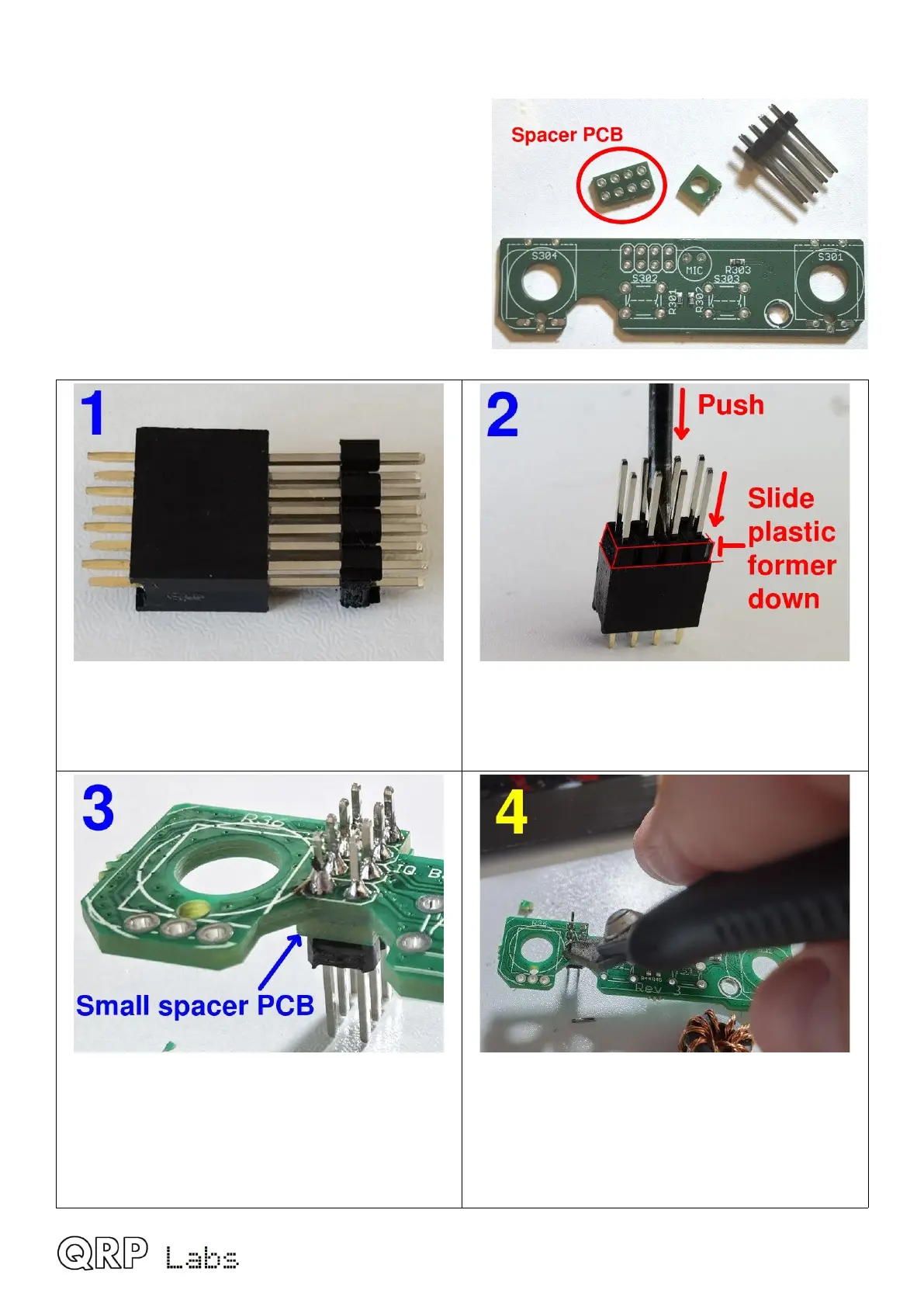
2.22 Install 2x4-pin male header on controls PCB
Next comes the assembly of the controls PCB,
which holds two rotary encoders and the two tactile
switch buttons.
The supplied 2x4-pin header has longer pins (about
17mm).
The 2x4-pin header must be installed with the small
spacer PCB (see photo, right) sandwiched between
the connector body and the underside of the PCB.
Carefully follow the steps below to install this part.
Insert the long pins into the 2x4-pin header
socket (that will already be installed on the main
QMX PCB, in reality, but is shown separately
here for clarity).
Use a screwdriver to firmly push down on the
plastic former of the 2x4-pin header as shown,
to slide it down the long pins until it sits flush on
the 2x4-pin socket body.
Thread the small spacer PCB onto the top side
of the pins, and insert them into the controls
PCB from below (silkscreen up, as shown), then
solder carefully on the top side, ensuring no
shorts. The spacer PCB is important! Don’t
forget it to install it!
Use wire cutters to cut off the excess length of
the long pin headers. They need to be trimmed
otherwise they will risk touching the metal of the
enclosure when the QMX is installed in its
enclosure.
QMX assembly Rev 1.00e 50

 Loading...