2.21 Install 20K trimmer potentiometer R47
The 20K single-turn trimmer potentiometer allows adjustment of the LCD contrast.
This potentiometer has four little feet, one in each corner. Unfortunately these make the trimmer
too high and it may prevent the PCB from sliding into the QMX-mini enclosure later. Therefore it is
necessary to cut off the protruding feet using a wire cutter, so that the potentiometer can sit flat on
the PCB.
Follow the steps below to install this part.
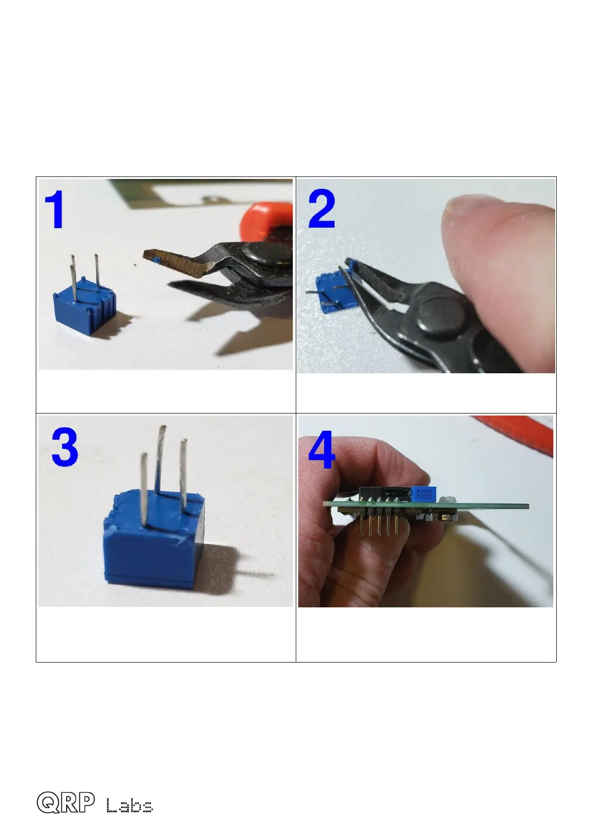
Cut each little plastic foot using wire-cutters.
It doesn’t matter if the corner of the
potentiometer body is damaged slightly.
In the end it could look like this.
Install and solder, with the potentiometer body
sitting flat on the PCB as shown. Trim excess
pin length from the bottom side.
QMX assembly Rev 1.00e 49

 Loading...