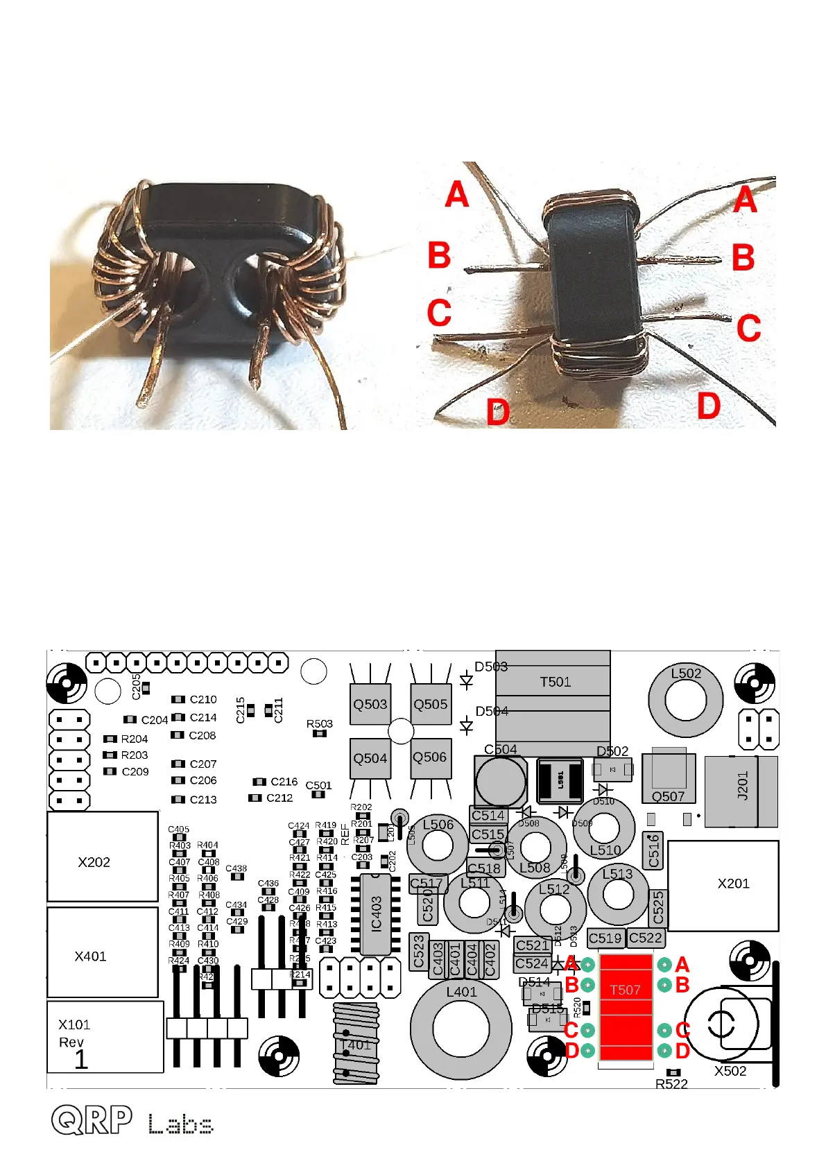
2.14 Wind and install transformer T507
Cut two lengths of 0.33mm wire, each approximately 25cm long. Wind 10 turns through each hole
of the BN43-1502 binocular core. Cut two 25mm lengths of 0.60mm wire. These are threaded only
ONCE through each hole.
The transformer is installed as shown on the diagram. The 0.60mm wire single-turns (ONE time
through the hole) are installed at B-B and C-C. The enamel needs to be scraped off the ends
before installation but not tinned (it would not fit in the holes). The thinner 0.33mm ends of the 10-
turn windings are fitted at A-A and D-D.
The transformer is designed to sit in the cut-out of the PCB. This is so that when the controls
board is installed above it, the height of the transformer binocular does not clash with the bottom
of the right-hand rotary encoder body. It should protrude about 1mm below the bottom surface of
the PCB. You can adjust the 10-turn windings, pushing them around the core such that they are
on the top side of the PCB, to achieve this. BEFORE soldering.
QMX assembly Rev 1.00e 40

 Loading...