There are numerous SMD components in the vicinity so be VERY careful when soldering the wires
of toroid T401, NOT to touch any of the nearby SMD components!
Once again my
method involves
holding the iron and
plenty of solder on
the joint for at least
10 seconds to make
sure the enamel
burns off
completely.
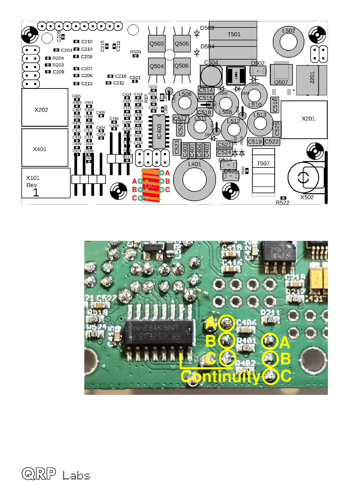
The photograph
(right) shows the
trifilar wire ending
holes labeled A B C
on the lower side of
the PCB. You
should check for
continuity between
all these. A, B, C
and pin 7 of IC402 are all connected together.
They are also connected to pins 7 and 9 of IC403 which is the 74CBT3253 on the top side of the
board.
QMX assembly Rev 1.00e 39

 Loading...