2.30 QMX GPS interface and PTT output
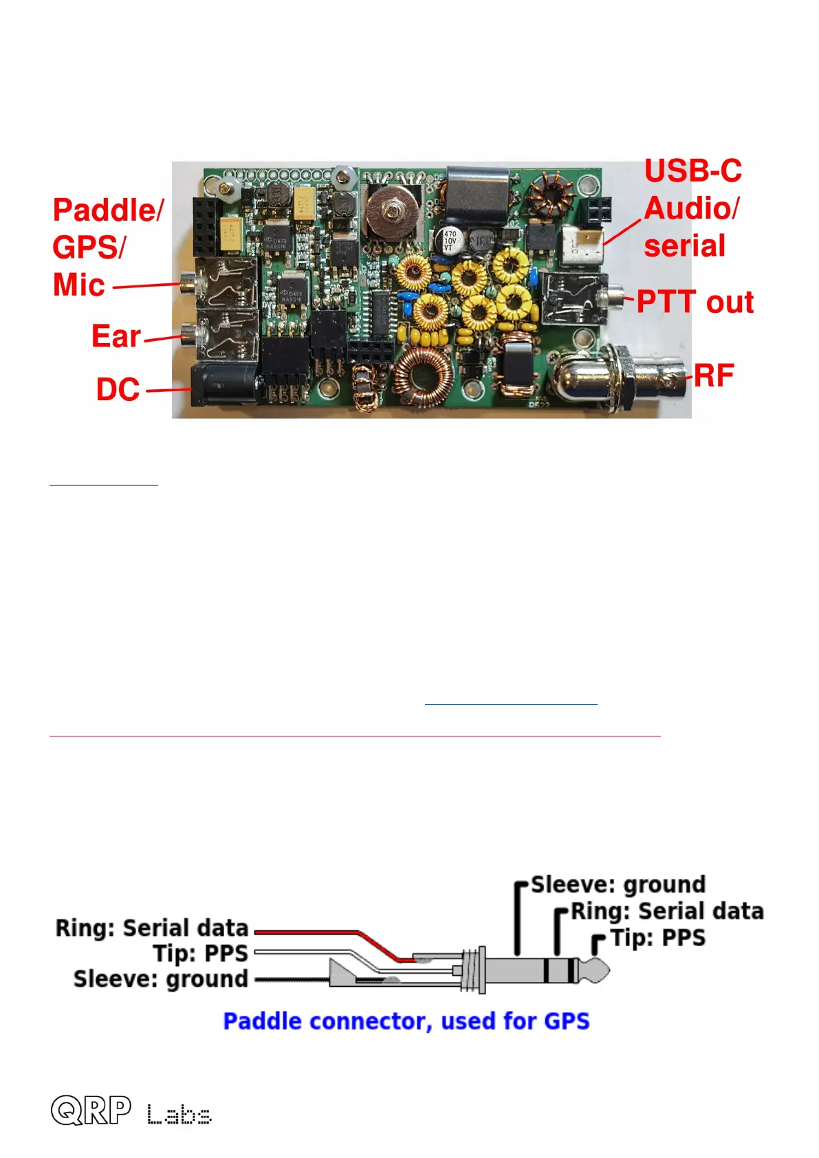
The picture below shows the connectors on the main QMX PCB.
GPS interface
The QMX transceiver has a GPS interface which can be used to:
• Calibrate the 25MHz TCXO reference oscillator
• Keep the oscillator disciplined and drift-free (frequency and time) during WSPR beacon
operation
• Set the internal Real Time Clock, which is critical for WSPR options and may be displayed
on-screen if you have configured it.
The GPS produces two output signals, PPS (Pulse-per-second) and RxD (Serial data). A GPS
such as the QRP Labs QLG2 is perfect for this see http://qrp-labs.com/ql g2
QMX cannot supply +5V for the GPS unit; you need to provide that separately.
The GPS signals (PPS and RxD) use the same microcontroller pins as the paddle Dah and Dit
respectively. Therefore you cannot use the Paddle and GPS at the same time. In fact, you should
only connect the GPS during the calibration of the reference frequency, and while operating the
QMX as a beacon (CW, FSKCW or WSPR).
The following diagram shows the connections.
QMX assembly Rev 1.00e 59

 Loading...