Solder each of the five switch pins, on the
underside of the PCB (the side with the blue
body of the rotary encoder). The center pin of
the three may benefit from a piece of wire off-
cut to extend it to reach the PCB hole.
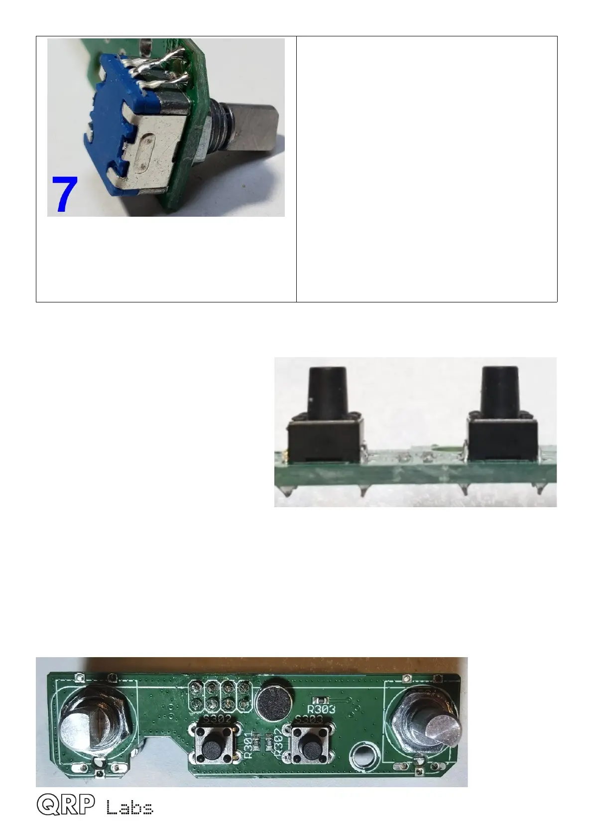
2.24 Install tactile switch buttons
The two buttons should be installed on the
control PCB as shown. These have four pins
on a rectangular footprint that can only fit
into the PCB one way. The only special
precaution to observe here, is to make sure
that the switch button is seated squarely on
the PCB, so that the shaft is perpendicular to
the PCB. Solder two diagonally opposite pins
first then check the alignment and make any
adjustments necessary; when all is well,
solder the two remaining pins.
2.25 Install electret microphone
The QMX kit contains an electret microphone which will facilitate future SSB mode support. Install
and solder the supplied 6mm electret microphone on the controls PCB. The pins need to be
spread apart slightly and it will not sit completely flush on the PCB. Microphone POLARITY is
critical! It is essential to fit the microphone so that the pins fit exactly in the silkscreen
circle as shown below.
QMX assembly Rev 1.00e 52

 Loading...