2.19 Install 2x5-pin and 2x2-pin male pin header connectors
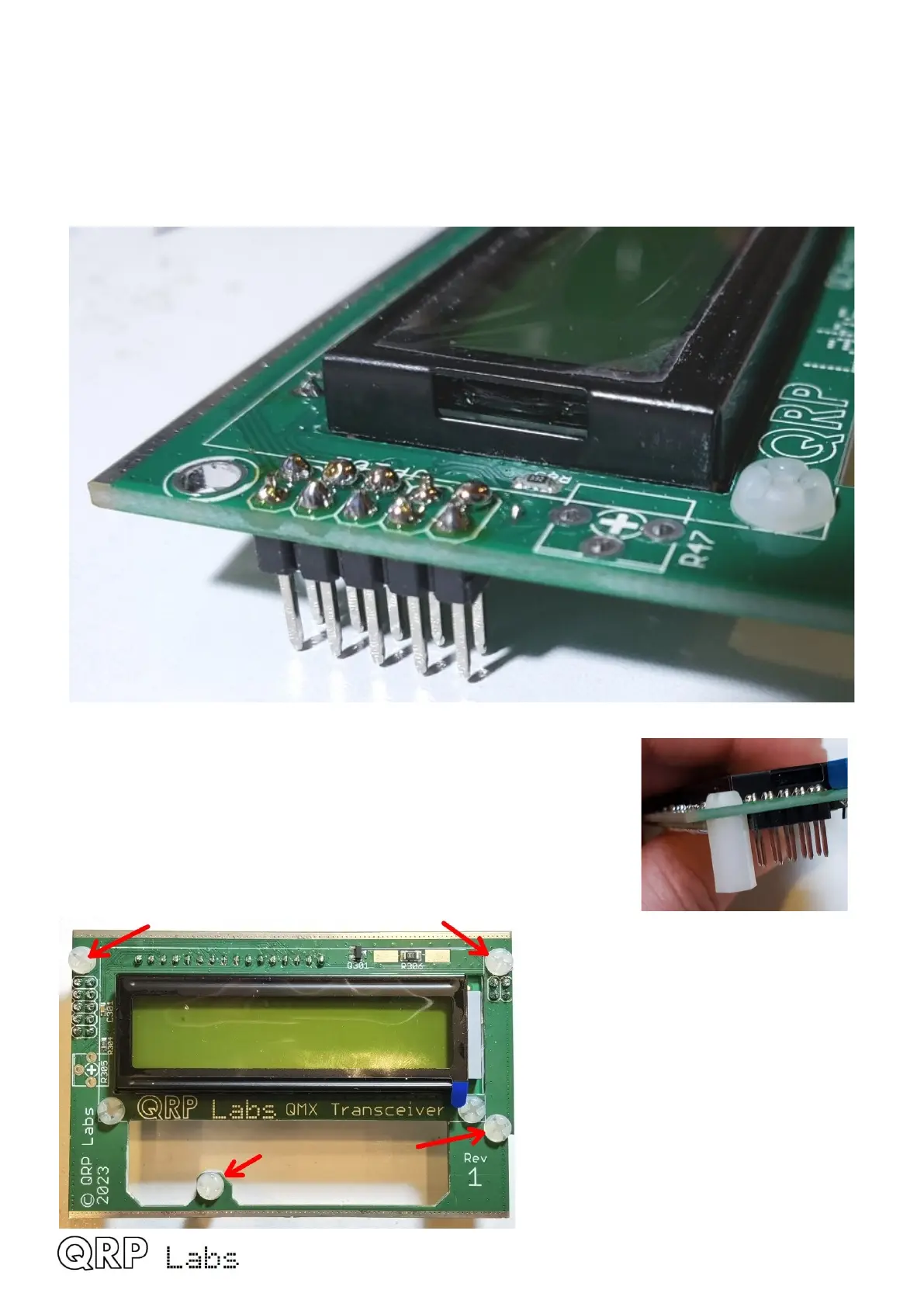
Install the 2x5-pin male header from below the display PCB; the short-end of the pins should be
inserted through the PCB from the bottom side, as shown. Solder one pin first, and check
alignment before continuing with the other nine. Try to ensure that the pin header sits squarely and
centrally in its allocated position. Install and solder the 2x2-pin male header similarly on the right-
hand side of the board.
2.20 Install four 11mm nylon spacers
Install four 11mm nylon hex spacers on the underside of the LCD PCB
using four 6mm nylon screws as shown.
Ensure the hex spacers are positioned such that a flat side is parallel
to the nearby PCB edge, so that no corners overhang the edge of the
PCB, which would prevent the enclosure end panels fitting.
QMX assembly Rev 1.00e 48

 Loading...