2.31 FINAL CHECKS BEFORE APPLYING POWER THE FIRST TIME!
It’s very highly recommended to check everything very carefully before applying power, as follows:
1. Look over the entire board with optical magnification and look for any dry joints, solder
bridges or whiskers, components which were not soldered properly, etc.
2. Note that the QMX is normally supplied without firmware and you must install firmware first,
before anything will happen (see next section after finishing this “final checks” section).
3. Check that there is no short-circuit between the body of the left rotary encoder, and the DC
input jack power connector.
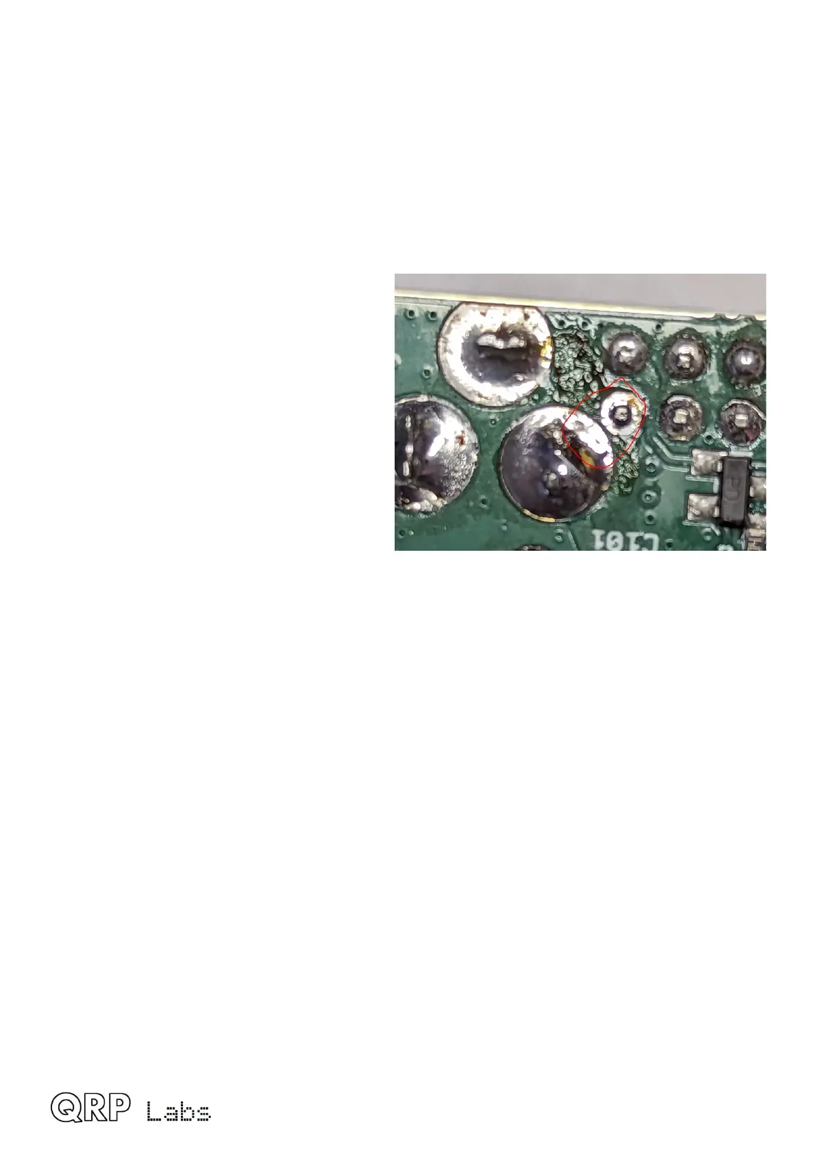
4. Check particularly that there is no solder
bridge between the rear pad of the
2.1mm DC power barrel connector, and
the nearby corner pin of the 2x4-pin
right-angled header which connects to
the 5V buck converter board. The
clearance between the two pads is very
narrow and a solder bridge here will
absolutely fry your QMX irreversibly and
permanently. So make sure there is no
solder bridge…
5. The plug-in buck converter boards are
critical, because they supply power to
the 3.3V and 5V rails. If there are any
faults here, it could destroy your QMX instantly.
6. Check the soldering of the 2x4-pin and 2x3-pin right-angled headers which connect to the
plug-in buck converter boards. Look for dry joints and any solder bridges or other faults.
Check the “edge connected” female pin header sockets on the plug-in boards themselves –
are all the pins properly soldered, and no accidental solder bridges between pins?
7. Make sure the two buck-converter boards are properly plugged in, and each one is secured
with its retaining screw (10mm M3 plastic screw and two M3 plastic nuts). The QMX cannot
function without the two buck-converter boards.
8. Make sure that the controls board connector is properly soldered in and the board is
installed correctly and secured with its mounting pillar and screw; the left rotary encoder
shaft button must later be pressed (long press) to switch on the unit (see next section).
9. When you apply power to your QMX fo rthe first time, it is a very good idea to use a lower
supply voltage than you intend to run at, perhaps 7V for example; and use a current-limited
supply if possible, perhaps limited to say 250mA. If there are any problems, this will
minimize the probability of damage.
10.When you do finally dare to apply the power, you should see ZERO current consumption,
and nothing happen; then press the left rotary encoder button; with a USB cable plugged in,
QMX should appear the first time as a USB Flash drive (memory stick) so that you can
install the firmware.
QMX assembly Rev 1.00e 61

 Loading...