EasyManuals Logo
Home>QRP Labs>Transceiver>QMX

QRP Labs QMX Assembly Manual

QRP Labs QMX
66 pages
To Next Page IconTo Next Page
To Previous Page IconTo Previous Page
Page #54 background imageLoading...
Page #54 background image
2.27 Fit Controls PCB to main PCB
Now fit the Controls PCB to the main PCB by plugging together the two 2x4-pin header
connectors.
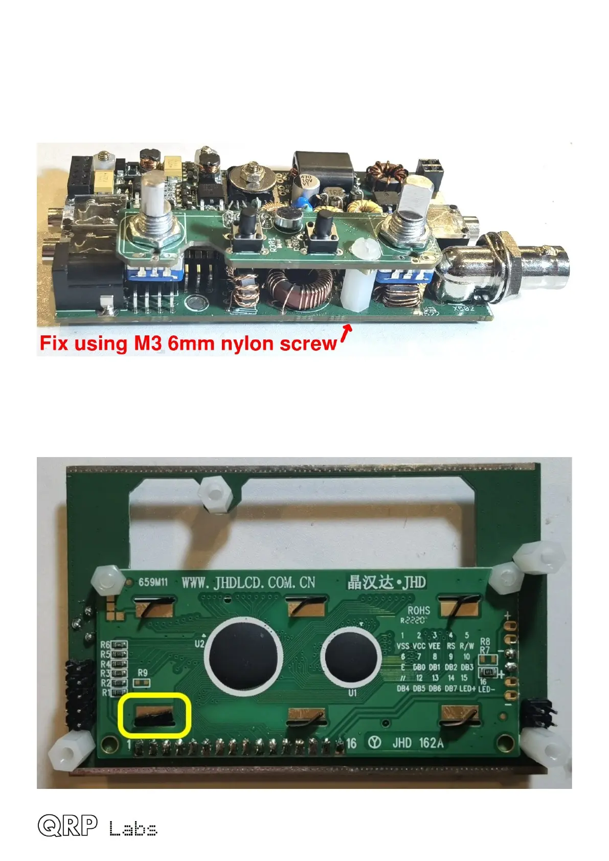
Fit an M3 6mm screw from the underside of the main PCB, screwed into the 11mm nylon hex
spacer pillar that is fixed to the Controls PCB, as shown in the following photograph.
2.28 Plug together the boards
There is a mechanical conflict between the black metal LCD module assembly retaining tab
nearest to the 2x5-pin header, and one of the 330uH inductors on the power supply boards.
QMX assembly Rev 1.00e 54

Other manuals for QRP Labs QMX

Questions and Answers:

Question and Answer IconNeed help?

Do you have a question about the QRP Labs QMX and is the answer not in the manual?

QRP Labs QMX Specifications

General IconGeneral
BrandQRP Labs
ModelQMX
CategoryTransceiver
LanguageEnglish

Related product manuals