2.23Install rotary encoders
Each rotary encoder is installed on the controls PCB, according to the following steps:
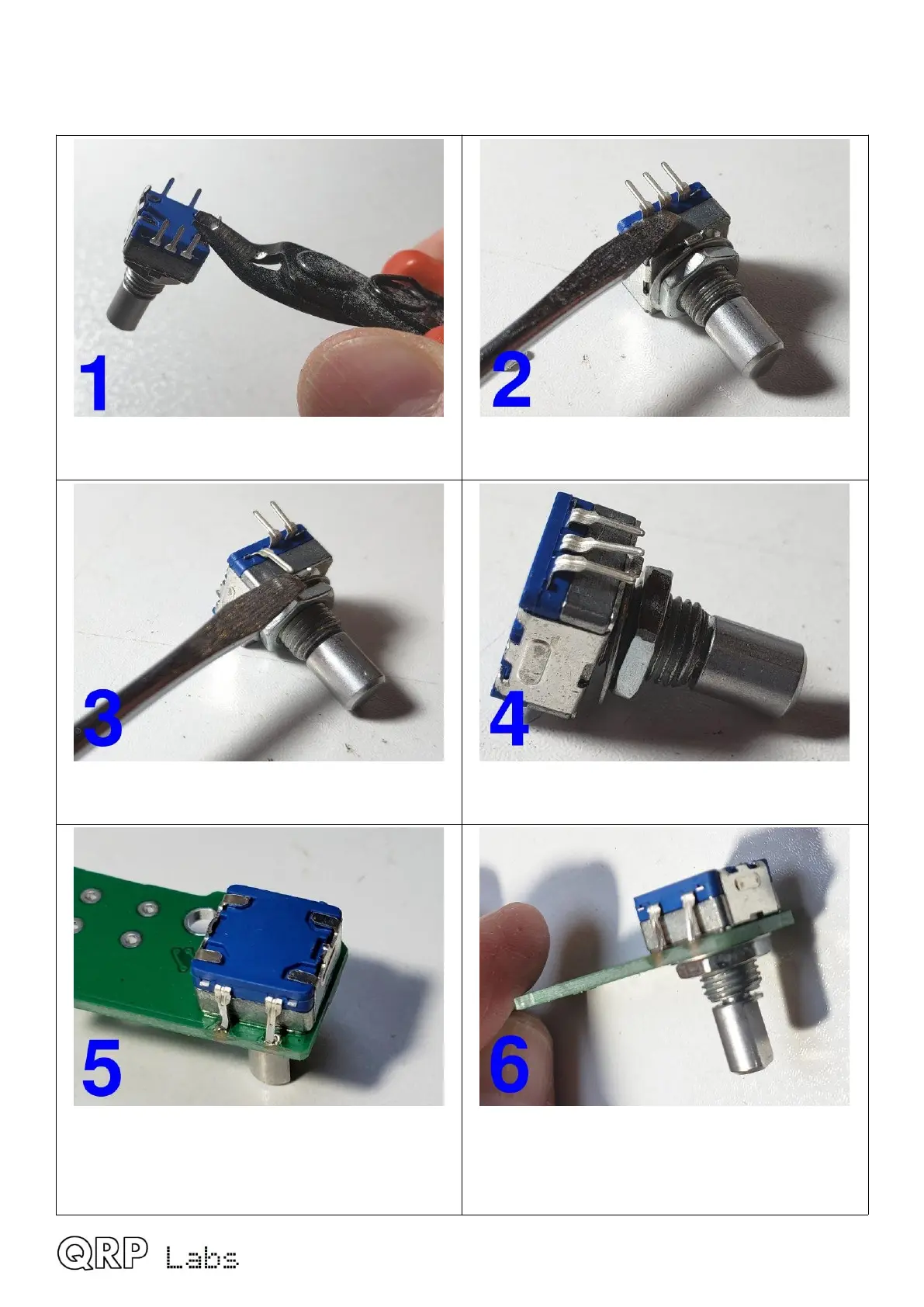
First cut off two large PCB-mounting lugs as
shown using wire-cutters. Do NOT cut pins.
Position a flat-headed screwdriver above one of
the five switch pins.
Bend over the pin through 180-degrees so that
it points to the front of the control.
Repeat the same procedure for the four
remaining pins.
Install the rotary encoder, first line up pins so
that they fit in corresponding PCB holes. The
rotary encoder has a locating tab which fits into
a matching hole on the PCB.
Make sure the nut is on the “top” (silkscreen-
printed) side of the PCB.
Do not use the washer.
Tighten the nut.
QMX assembly Rev 1.00e 51

 Loading...